IBM DCS9550 1S1 manual Ops Panel LEDs, Led

Page 50

Operation

3.2Ops Panel LEDs

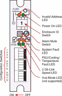
The Ops Panel LEDs fault and status conditions are defined in Table 3-2 and shown in Figure 3-1.

Figure 3–1Ops Panel LEDs and Switches

Please refer to Chapter 4, Troubleshooting and Problem Solving for details of any fault indication.

Table 3–2Ops Panel LED States

LED

Definition

Color

Normal

Fault


Status

Status


Invalid

Indicates that an invalid Enclosure

Amber

Off

Flashing

Address

ID has been selected or that the


selection has changed after Power


On


Power On

Enclosure Powered On

Green

On

Off


System Fault

System/SCM Fault

Amber

Off

On


PSU/Cooling

PSU Cooling fault or enclosure

Amber

Off

On

Fault

over-temperature.


IBM System Storage DCS9550 1S1 Storage Expansion Unit Installation, Service, and User Guide

35

Image 50
Contents IBM System Storage Page Preface International Standards Safety Guidelines Figure P-3PSU/Cooling Module Caution Label Figure P-5 PSU Safety Label Electric Shock Hazard Inside Class 1 Laser Product Avis de conformité à la réglementation d’Industrie Canada ESD Precautions Data Security Taiwan Contact Information How to Send Your Comments Page Page Contents Xiii Introduction IBM System Storage DCS9550 1S1 Storage Expansion UnitEnclosure Chassis 2Enclosure Chassis FrontPower Supply/Cooling Module Multiple Power Supply/Cooling ModulesOps Panel Indicators and Switches Operators PanelDCS9550 Controller Settings SCM Input/Output Module6SCM I/O Module 7SCM Front Panel as viewed from rear of Enclosure Sata Dual Path Transition Card Drive Status IndicatorsDrive Carrier Module Blank Modules Anti-tamper LocksDummy Carrier Modules AC Power 450W PSU DimensionsWeight PSU Safety and EMC ComplianceEnvironment AirflowInterfaces SCM I/O Module SpecificationDrive Carrier Module Specification Software Enclosure Services SES Support This page is intentionally blank Installation Planning Your InstallationEnclosure Bay Numbering Convention 1Module locationsPre-Requisites Enclosure Installation ProceduresChassis Installation Parts Check List Rack Mounting Rail KitPower Supply/Cooling Module Procedure ProcedurePower Supply/Cooling Module Installation 2AC Power Supply/Cooling Module Handle in Open Position FC-AL Interface SCM I/O Module ConfigurationsInternal Loop Structures Unit 1-S Unit 2- S SCM I/O Module Installation 7IBM System Storage DCS9550 Couplet CablingSwitch Function Recommended Definition Number Setting Drive Enclosure Device AddressingSwitch Function Recommended Drive Configuration Row ColumnDrive Carrier Installation Parts Check List 10Installing a Sata Drive Carrier Module Engaging the Anti-tamper Locks Activating the LocksPower Cord Connection Parts Check List 13Activating the Anti-tamper LockGrounding Checks This page is intentionally blank Power On OperationPower Supply/Cooling Module LEDs AC PSUOps Panel LEDs LEDDisk Drives LEDs Power DownStarting the Drives Initial Start-up Problems Faulty Cords Emulation LimitationsLEDs Alarm Sounds On Power UpGreen Signal Good LED on SCM Not Lit Ops Panel LED SCM I/O Module LEDs Audible AlarmAudible Alarm Mute Power Supply/Cooling Faults TroubleshootingSystem Faults Power supplies Fitted Thermal ControlThermal Shutdown Thermal AlarmDrive Carrier Module Faults Replacing a Module Dealing with Hardware FaultsContinuous Operation During Replacement Inserting the Module 2Removing/Inserting an AC Power Supply/Cooling Module SCM I/O Module Removing the Module5Removing an SCM I/O Module Removal and Replacement 7SCM I/O Module Latch OperationIBM MTM 1269-1S1 Sata Disk Chassis FRUs Spare Parts and Ancillary ItemsThis page is intentionally blank Glossary Page Index System LED For additional information, visit the web at Trademarks Page Page Readers’ Comments We’d Like to Hear from You Business Reply Mail Page SC30-9738-00