GE 994-0089 user manual Hardware Overview, Features

Page 13

GE Energy

The D400 can be configured “online” through a standard Web browser or “offline” through the Offline Configuration Manager (OCM) - Future.
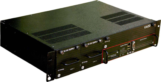
Hardware Overview

The D400 is built on a flexible, high-performance, expandable platform powered by a 650 MHz processor. It is distinguished by the noticeable lack of a hard drive and fan, employing instead the rugged and reliable CompactFlash mass storage solution.

The D400 supports various communication media types through a choice of input/output (I/O) adapter cards –

Serial (up to 8 configurable 2-port adapter cards): RS-232, RS-485, Fiber Optic (Glass or Plastic)

Ethernet: 10/100BaseT, 10BaseFL or 100BaseSX

Features

Secure Web server (128-bit encryption)

Secure SCADA communications through Secure Sockets Layer or Transport Layer Security (SSL/TLS)

Secure access using SSH (Secure Shell)/SCP (Secure Copy)/HTTPS

Secure terminal server, gateway, and/or data concentrator using SSL/TLS

User configurable security levels/access

Support for remote user authentication

Built-in alarm annunciator

Support for time synchronization signals, including Network Time Protocol (NTP) and

IRIG-B

Support for multiple SCADA protocols for communications to multiple masters

High-performance real-time database engine

D400 Substation Data Manager User's Manual 13

Image 13
Contents D400 Substation Data Manager Trademark Notices Copyright NoticeContents 994-0089-1.00-2, General Purpose About this DocumentIntended Audience Additional DocumentationDocument Conventions How to Use this GuideSearch Technical Support Product SupportContact Customer Support Product ReturnsGE Energy Before You Start Safety Precautions Symbol Meaning Regulatory Compliance Information RoHS Material Declaration Data Content by AssemblyCE Mark Compliance Restriction of Hazardous Substances RoHSProduct Overview Hardware Overview Features14 994-0089-1.00-2, General System Product SpecificationsCommunications Serial communications Signal PropagationRS-232 RS-485Physical ElectricalStorage Recommendations Battery LifeEnvironmental SoftwareInstallation Steps Installing the D400» Follow these main steps to install and set up the D400 Required Tools Unpacking the D400 Package ContentsShipping Inspection UnpackingFront Panel First Look at the D400Rear Panel Rack Mounting Physical Installation» To mount the D400 on a rack Panel Mount » To mount the D400 in a panelCommunication Cards Setting up Communication CardsD400 I/O Adapter Card Slots Network Slots 11 Types of Communication Cards» To change the settings on a communication card Changing Card SettingsFactory Default Configuration OptionsRS-232 Adapter RS-232 Adapter Top Side Switch SW1/SW2 ConfigurationDTE default Switch SW3/SW4 Configuration30 994-0089-1.00-2, General RS-485 Adapter RS-485 Adapter Top Side RS-485 Adapter Bottom Side Pull-up for TX+ Fiber Optic Serial Adapter Switch SW1 ConfigurationGE Energy IRIG-B Input Adapter Switch SW3 Configuration Switch SW2 ConfigurationIRIG-B Input Adapter IRIG-B Distribution Adapter IRIG-B Distribution AdapterPort Twisted-Pair Ethernet Switch Card 4-Port Twisted-Pair Ethernet SwitchHot Standby Fiber Optic Ethernet Switch Card Hot Standby Fiber Optic Ethernet SwitchRedundant TP Ethernet + COM2 Port Adapter Card Redundant Twisted-Pair Ethernet + COM2 Port AdapterCOM2 Port Adapter 11 COM2 Port AdapterUSB KVM Adapter USB KVM & Audio AdapterConnection Types Connecting to Devices and NetworksNetwork Local MaintenanceTime Synchronization Local Substation ComputerCabling Overview Media Designation Cabling ConnectorGeneral Cabling Requirements D400 Field and Network ConnectionsHigh-Voltage Installations RS-232 Connections Number Function Signal FlowCabling Requirements RS-485 ConnectionsIN/OUT Wire Connections 52 994-0089-1.00-2, General Glass Optical Fiber Fiber Optic ConnectionsPlastic Optical Fiber See .5 Fiber Optic Serial Adapter for configuration options IRIG-B Connections Fiber Optic Connector Signal Definitions FunctionIRIG-B Input Adapter IRIG-B Distribution Adapter » To connect a local PC to the D400 Network ConnectionsD400 Name Pin Ethernet Crossover Cable RJ-45 Pin Out D400 Switch/Hub NameColor Modem Connections Signal DB-9 DB-25 Pin # COM2 Port DB-9 Connector Signal Definitions PinCOM2 Port DB-9 to DB-25 Pin out Local HMI Connection D400 Front Serial Port DB-9 Pin Out Pin # Signal Front Maintenance PortPC Pin # D400 Pin # Signal » To connect your computer to the D400Power Supply Options Powering Up the D400Power Configurations Redundant Power SupplyPower Input Ranges Wiring Requirements Power Connections» To connect the power source to the D400 External Power RequirementsIf your power supply is… Then… SUPPLY1 SUPPLY2 input Power Source Configurations Connection Wiring DiagramPower Source Connection Wiring Diagram Power Fail Alarm Power Supply Alarms» To connect the Power Fail contact closure Wire the lamp between…System Fail Power Fail Alarm Connection» To connect the System Fail relay System Fail Alarm Connection System Status LEDs Front Panel LEDsD400 Front LEDs LED Display Status DescriptionSerial Port Status LEDs Connecting to the D400 for the First Time Configuring the D400» To connect to the D400 Under Function, arrow … » To configure the network interface GE Energy Default IP address is Servicing the D400 » To remove and re-insert the D400 main module Removing the D400 Main ModuleD400 Main Module D400 Battery Location Replacing the BatterySupported Battery Types Before You Remove the Battery…Supported battery replacements Manufacturer Mfg. Part Cleaning and Handling Lithium Batteries » To insert or replace the D400 batteryChecking Voltage Disposing of BatteriesChanging the CompactFlash User CompactFlash Access Panel» To change the System CompactFlash card » To change the User CompactFlash cardBefore You Remove the Power Supply… Replacing the Power Supply» To replace a D400 power supply unit D400 Power Supply UnitStandards & Protection Category Standard Name Description GE EnergyIeee Product Identification Ordering GuideSerial Communications Slots D400 Ordering GuideModification Record Authentication RecordVersion Rev Date Author Change Description