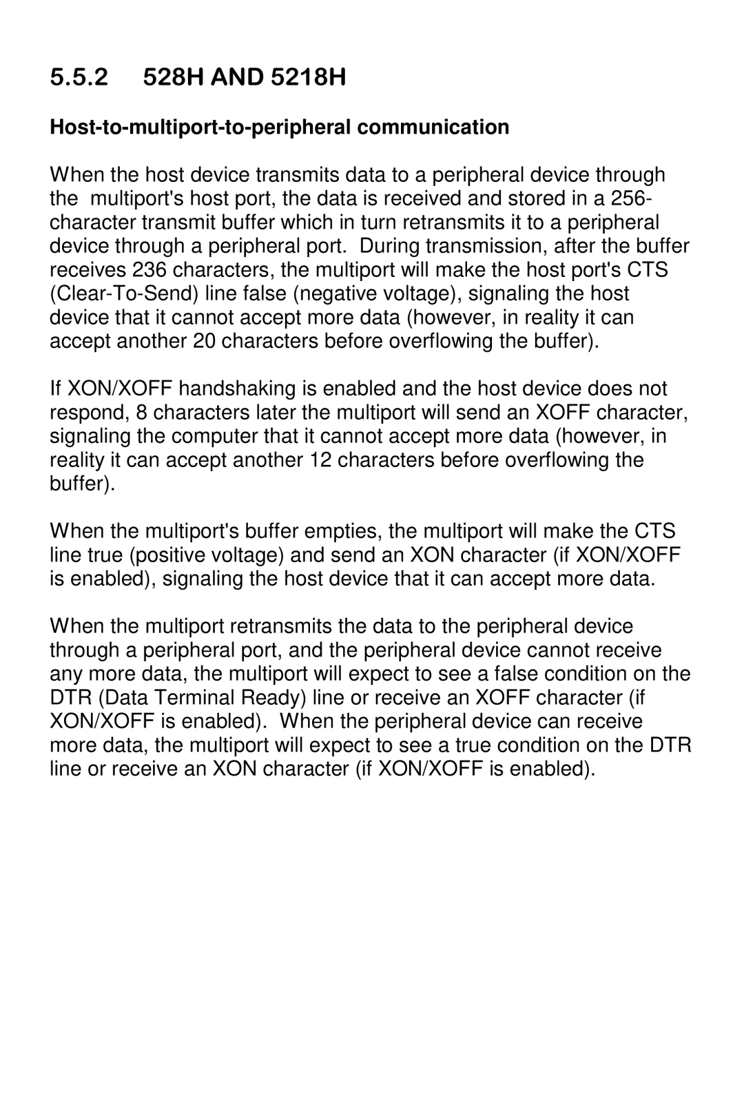
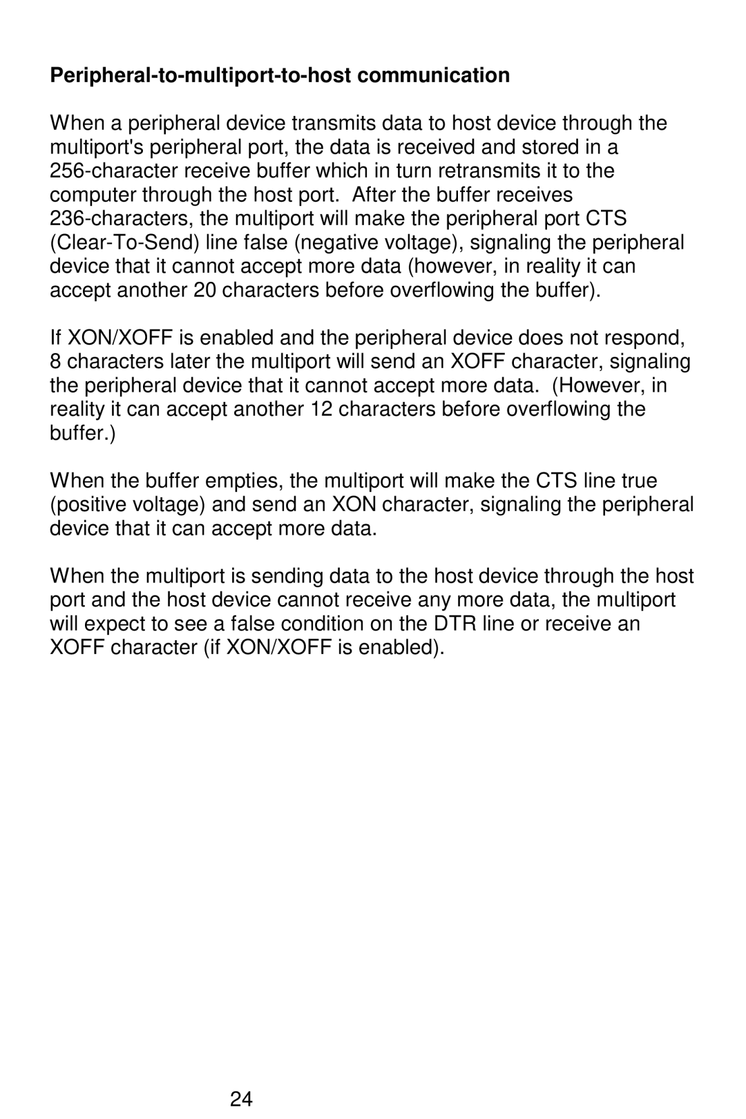
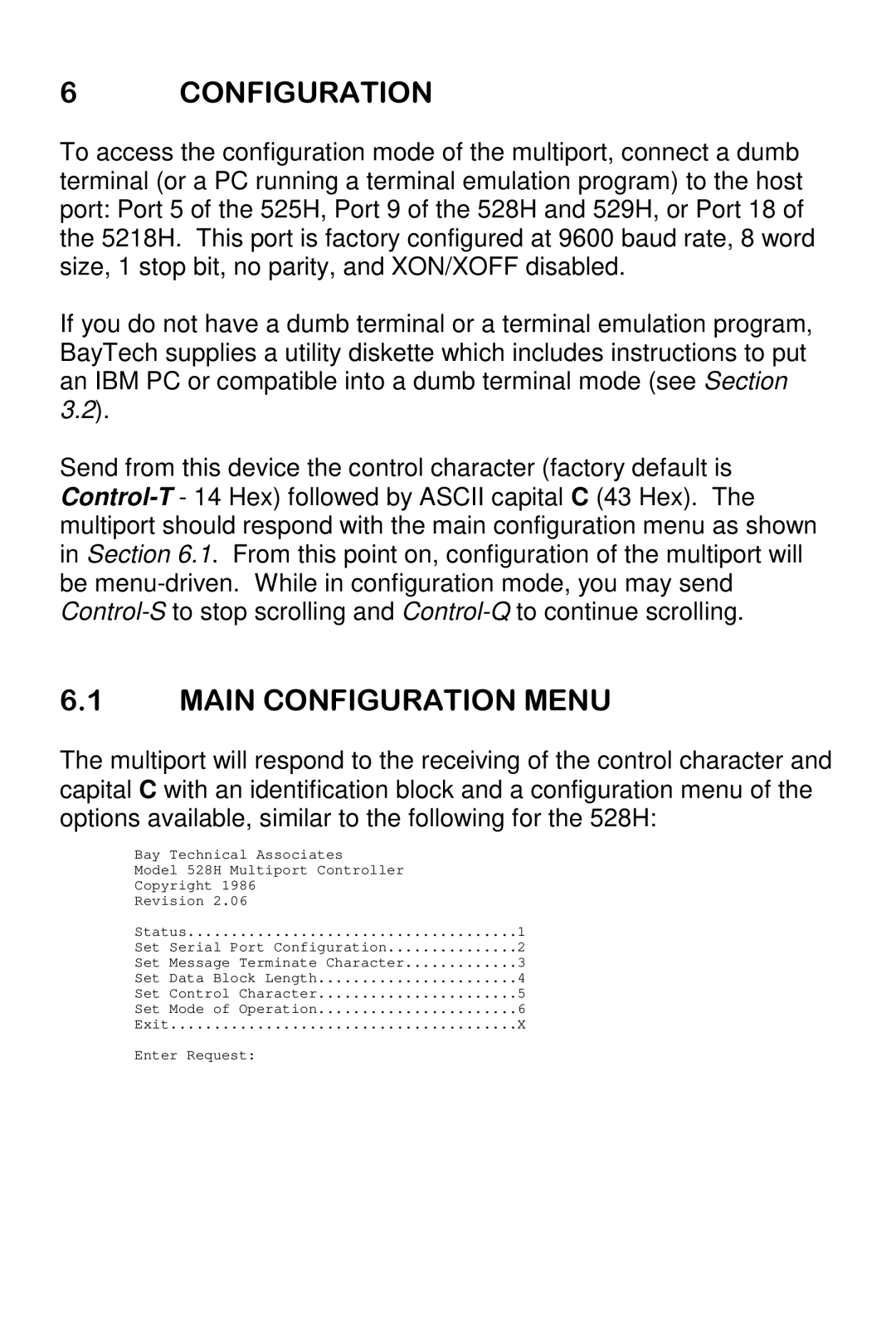
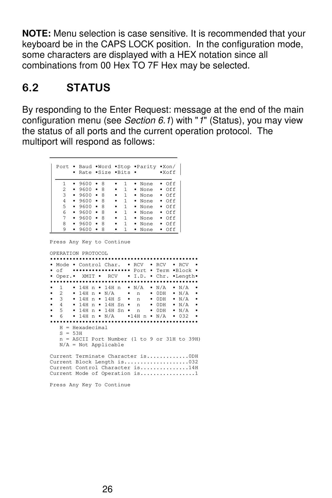
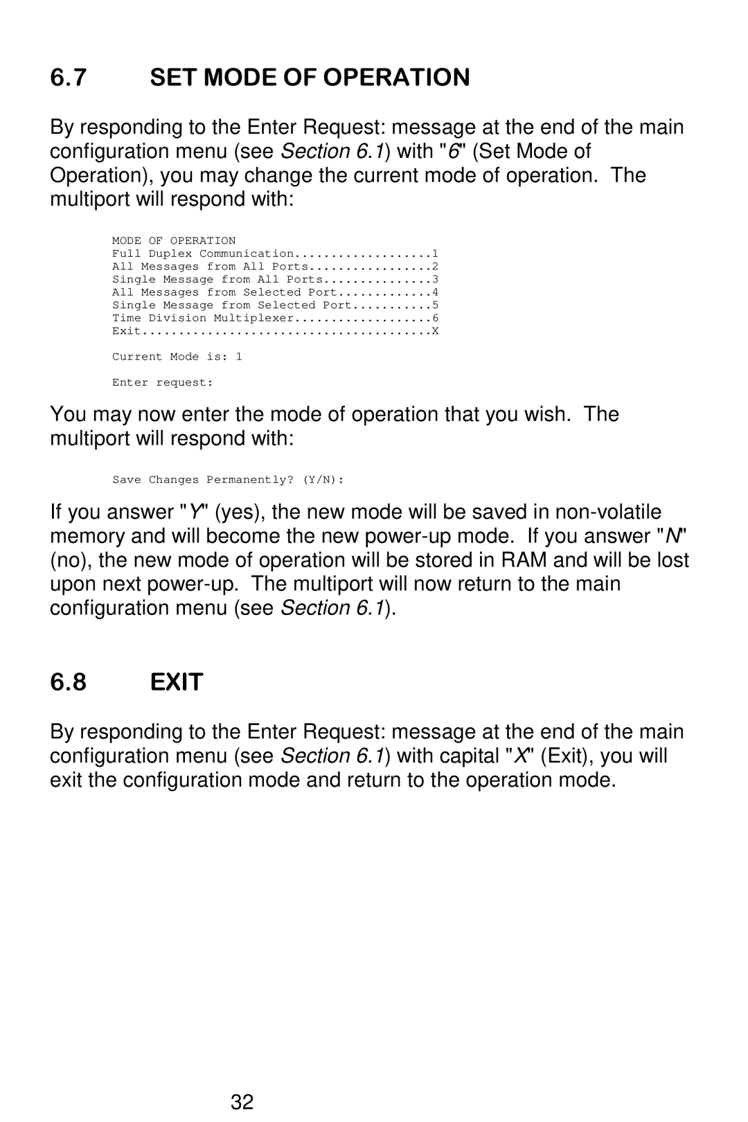
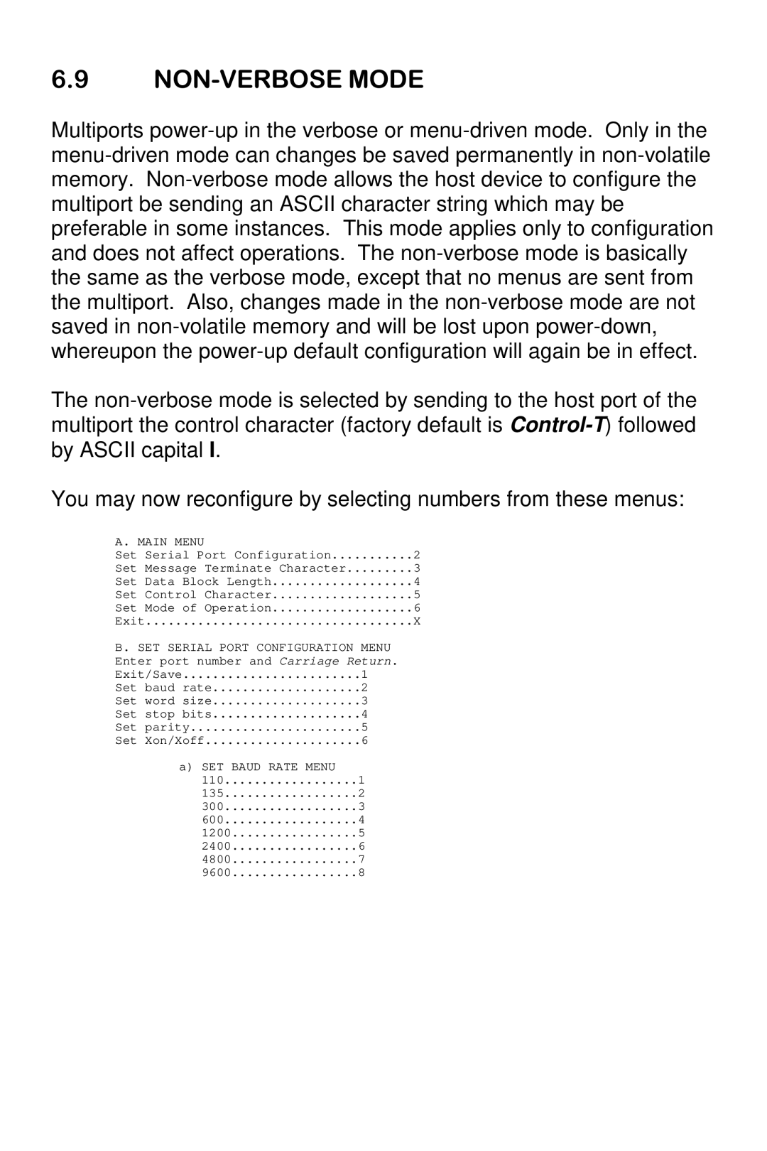
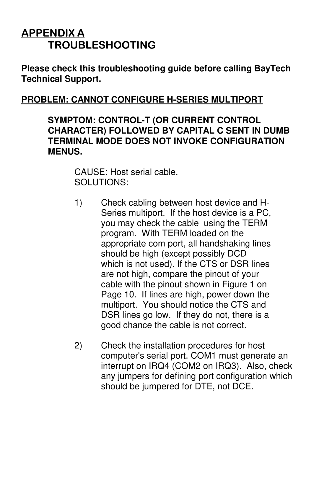
Bay Technical Associates 525H, 5218H, 528H, 529H owner manual SET Message Terminate Character

Page 39

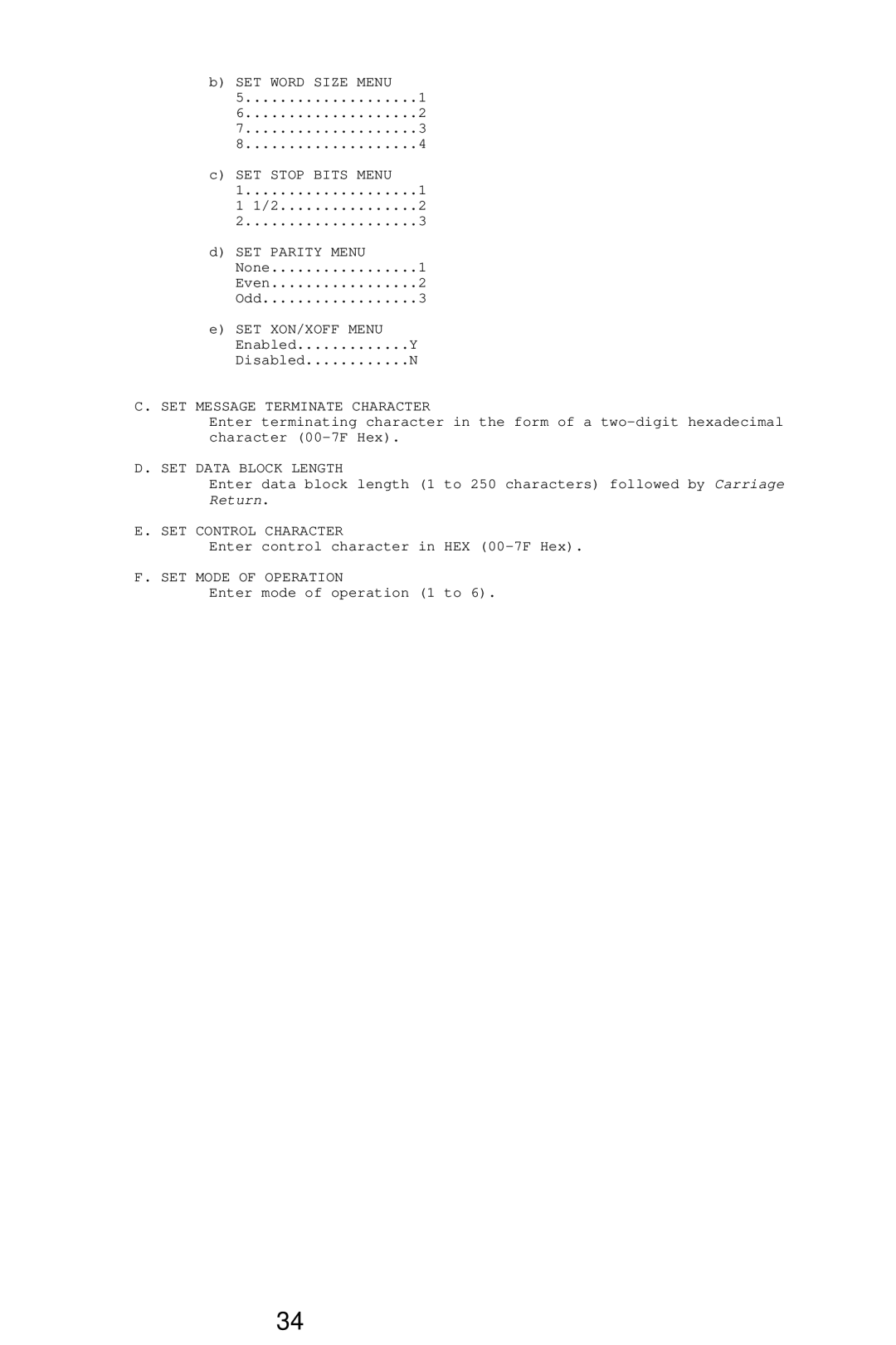
b) SET WORD SIZE MENU


5

....................

1

6

....................

2

7

....................

3

8

....................

4

c) SET STOP BITS MENU


1

....................

1

1

1/2

2

2

....................

3

d) SET PARITY MENU


None

1

Even

2

Odd

3

e)SET XON/XOFF MENU Enabled.............Y

Disabled............N

C. SET MESSAGE TERMINATE CHARACTER

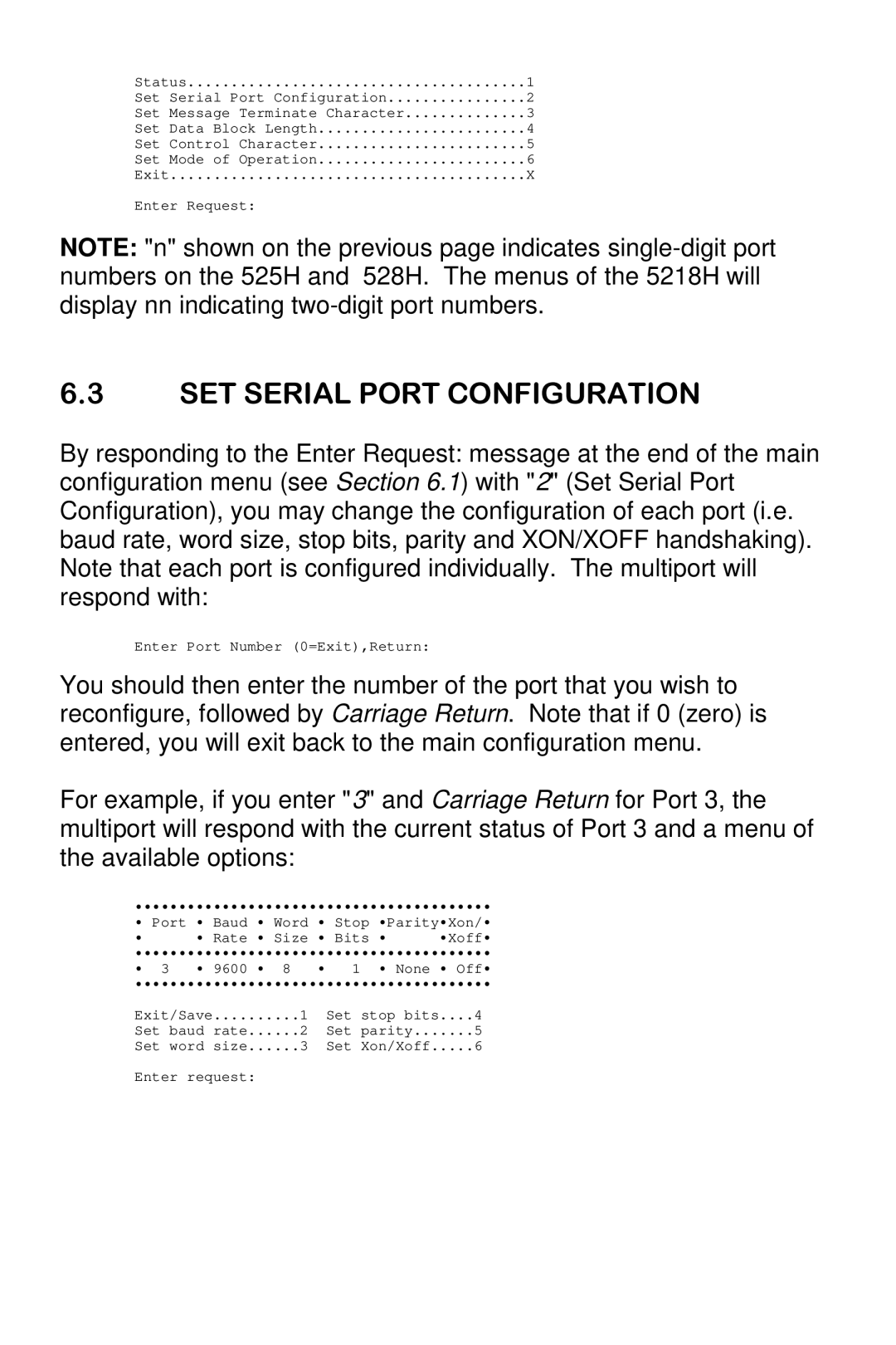
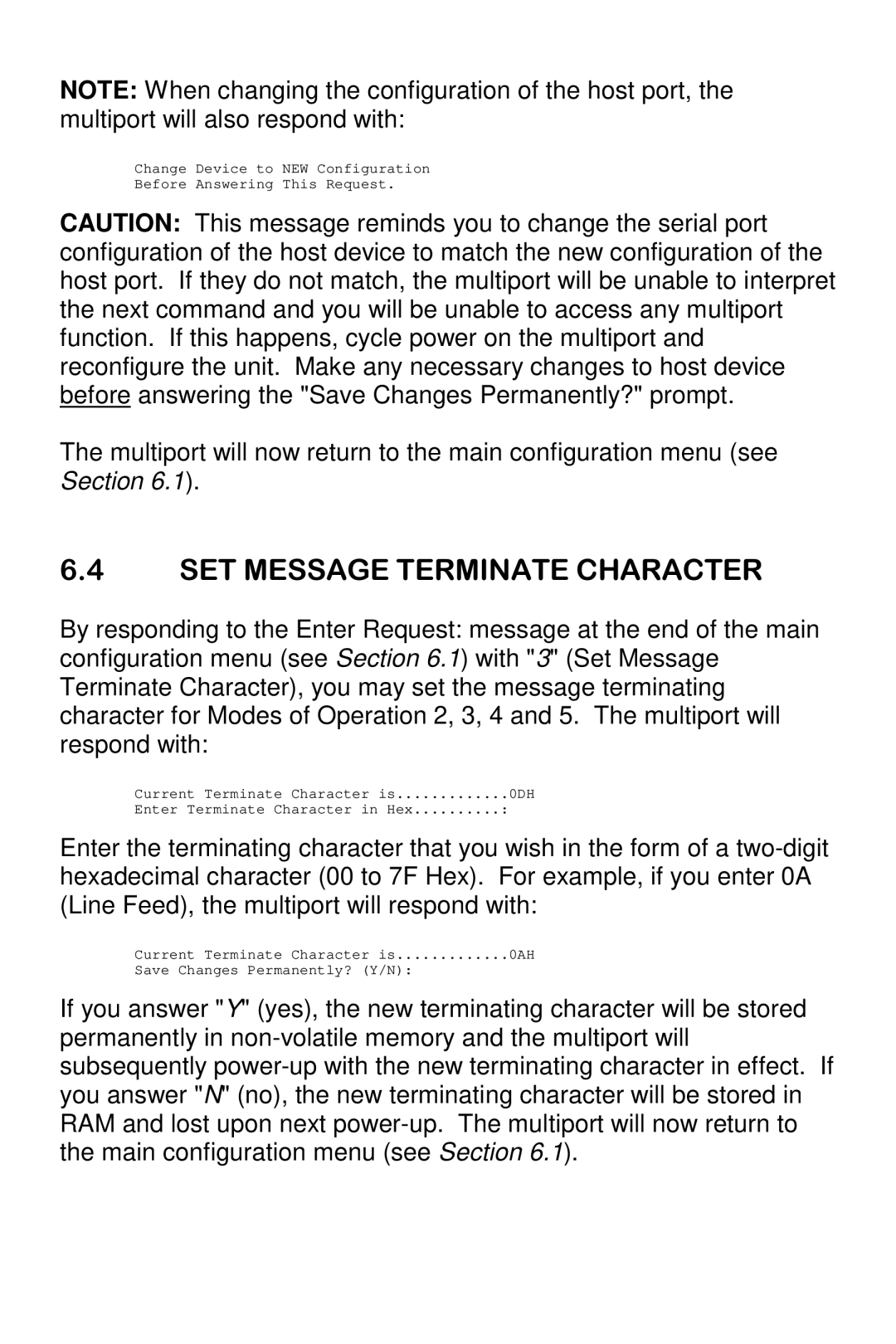
Enter terminating character in the form of a two-digit hexadecimal character (00-7F Hex).

D. SET DATA BLOCK LENGTH

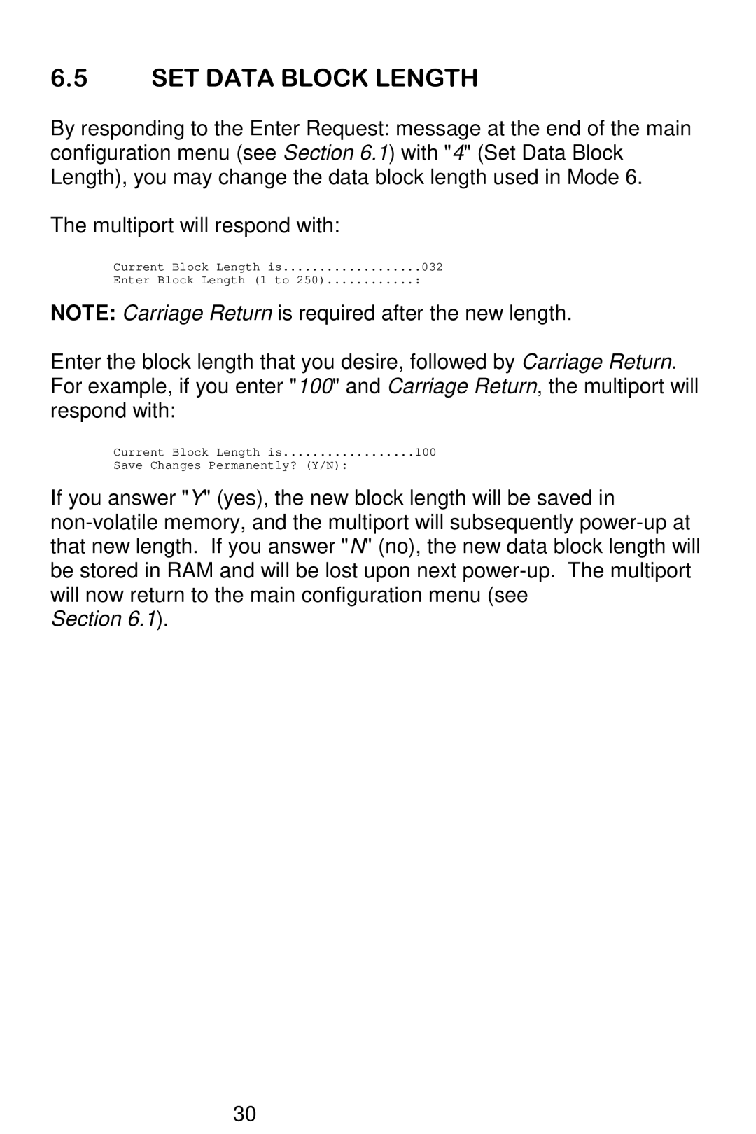
Enter data block length (1 to 250 characters) followed by Carriage Return.

E. SET CONTROL CHARACTER

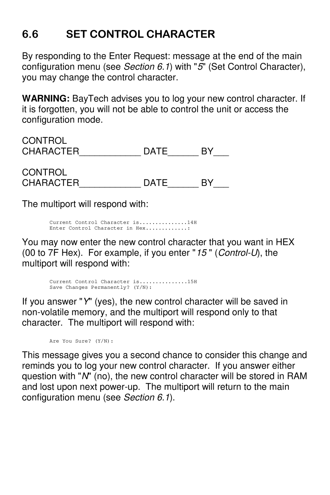
Enter control character in HEX (00-7F Hex).

F. SET MODE OF OPERATION

Enter mode of operation (1 to 6).

34
Image 39
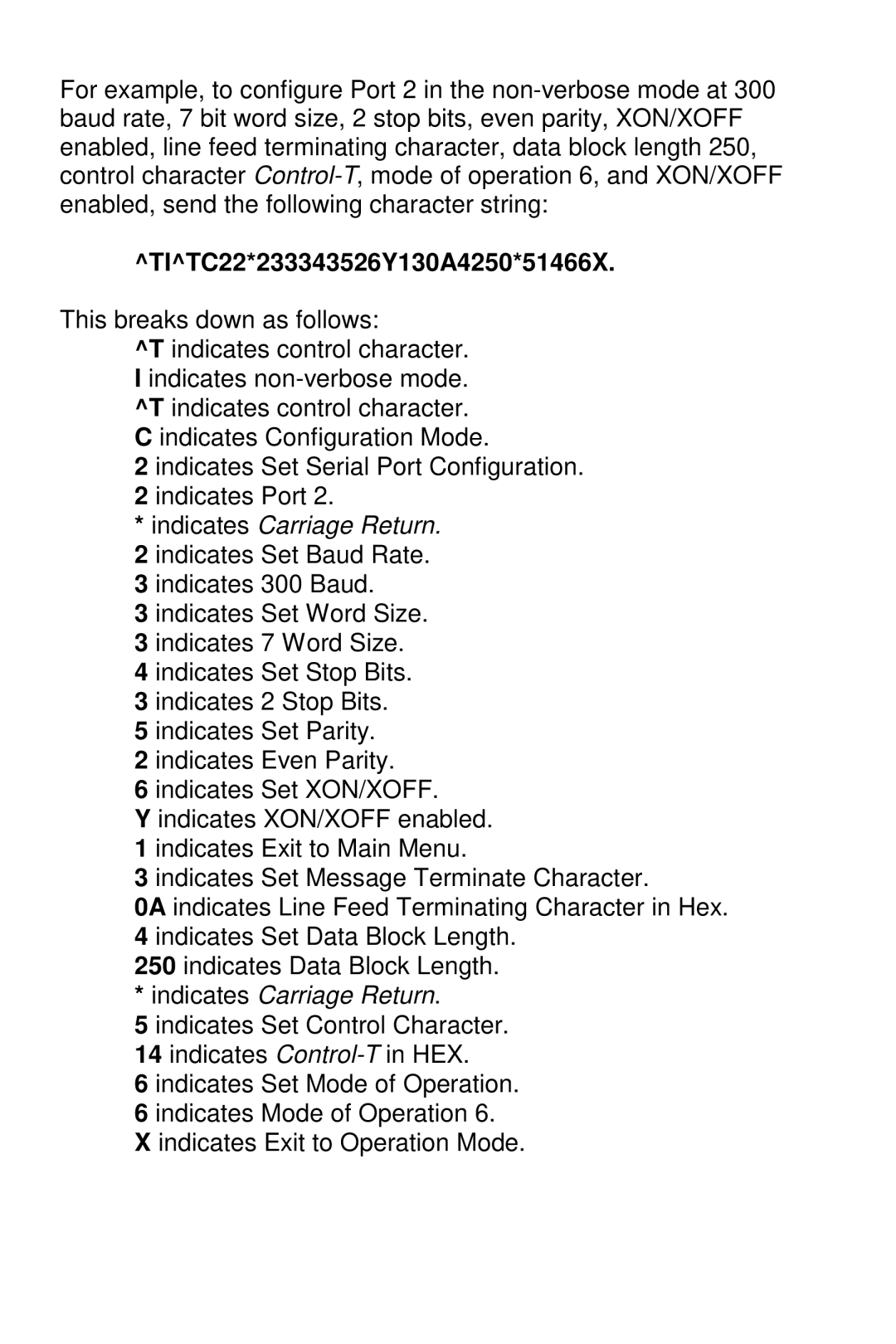
Contents Series Multiport Controllers Page Copyright 1993 by Bay Technical Associates, Inc Table of Contents Federal Communications Commission Radio Frequency Page Page Below shows six applications, one for each mode of operation USER-PROGRAMMABLE Configurations Factory POWER-UP Default ConfigurationsUL and CSA Listed Page Page Page DCE Port Signals 500H Series DCE to DTE Device Page Factory default is Carriage Return 0D Hex Page Page Page Page Page Page Page Page Host-to-multiport-to-peripheral communication Peripheral-to-multiport-to-host communication Host-to-multiport-to-peripheral communication Peripheral-to-multiport-to-host communication Page Operation Protocol Enter Port Number 0=Exit,Return For 110 135 300 600 1200 2400 4800 9600 Enter request 0AH Section Control Mode of Operation Main Menu SET Message Terminate Character TITC22*233343526Y130A4250*51466X Page Page Page Solutions Problem Garbage Data Symptom Missing Characters Symptom Random Garbage Characters Problem Cant Select Peripheral Port from Host Device Problem Cant Receive Data from Peripheral Ports Ccitt DOS Page Page Page Uart Other Baytech Products Page Page Series Multiport Controllers Page