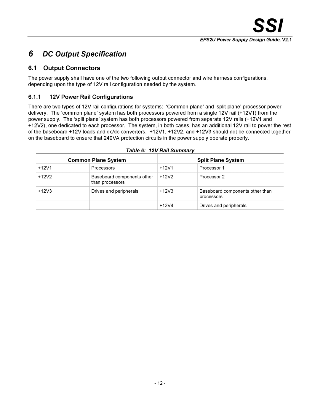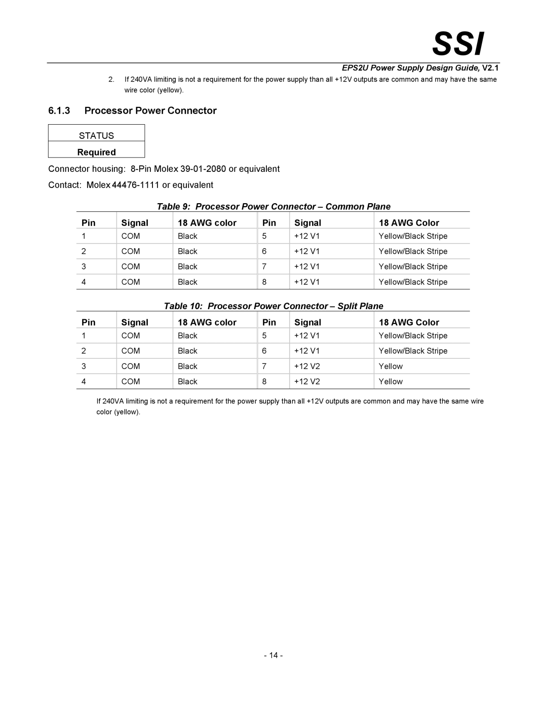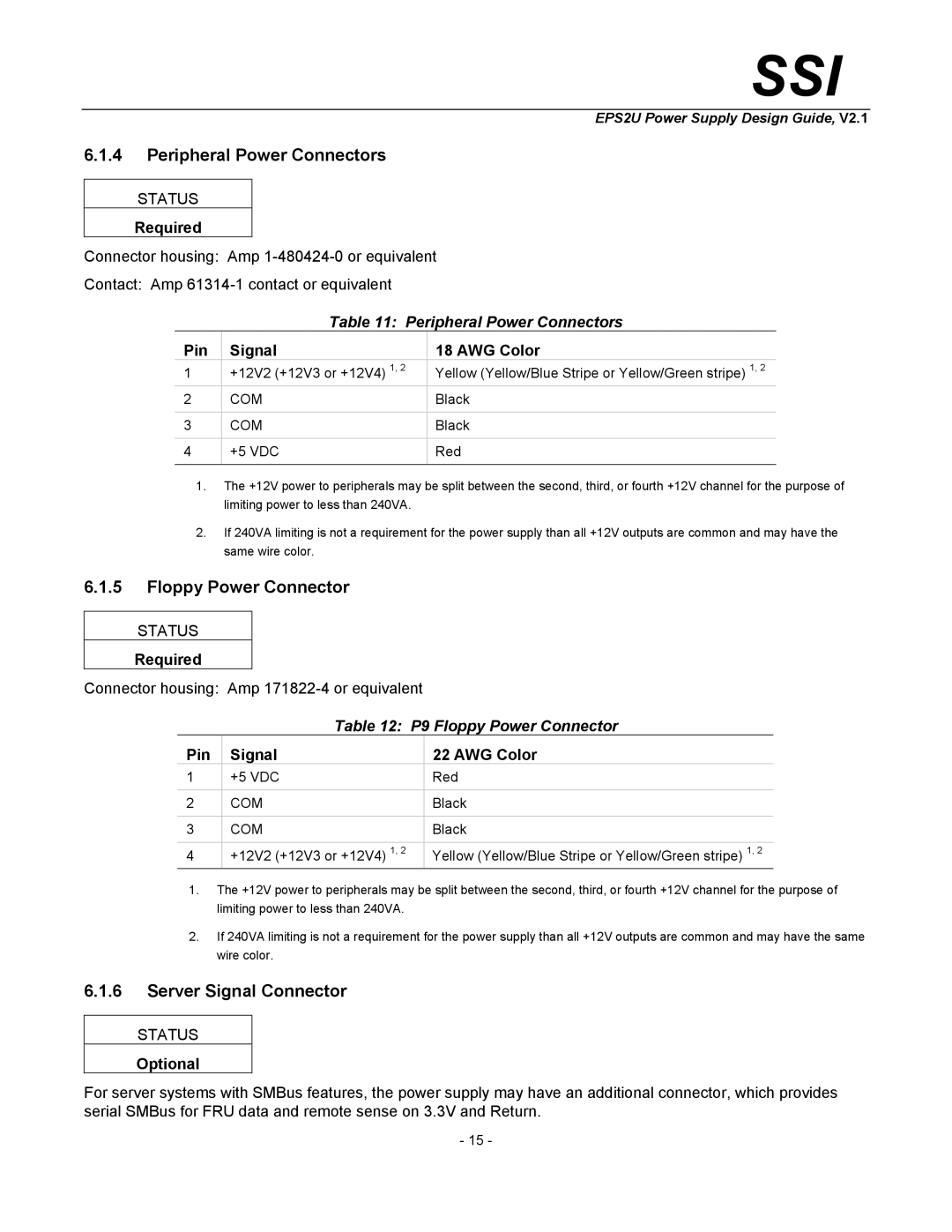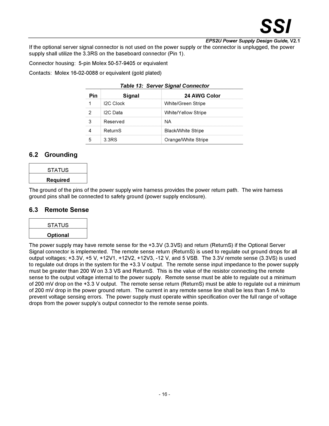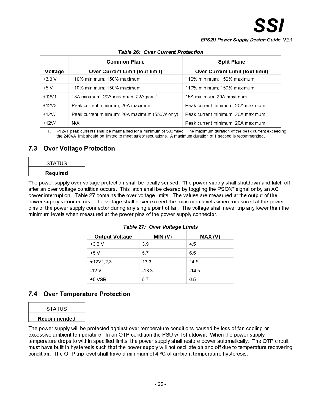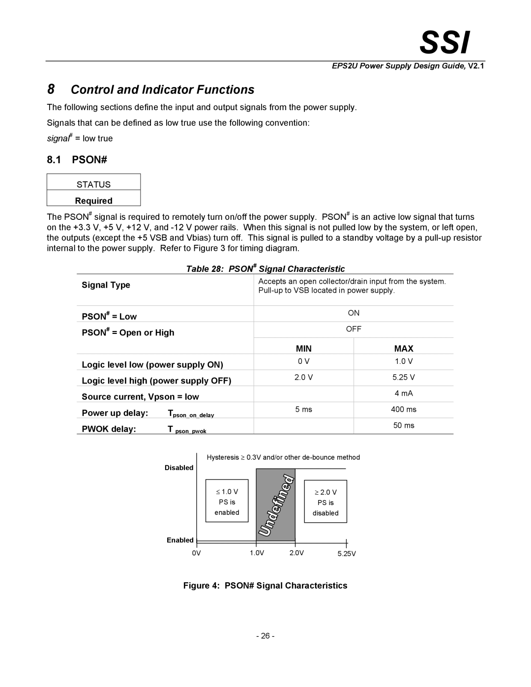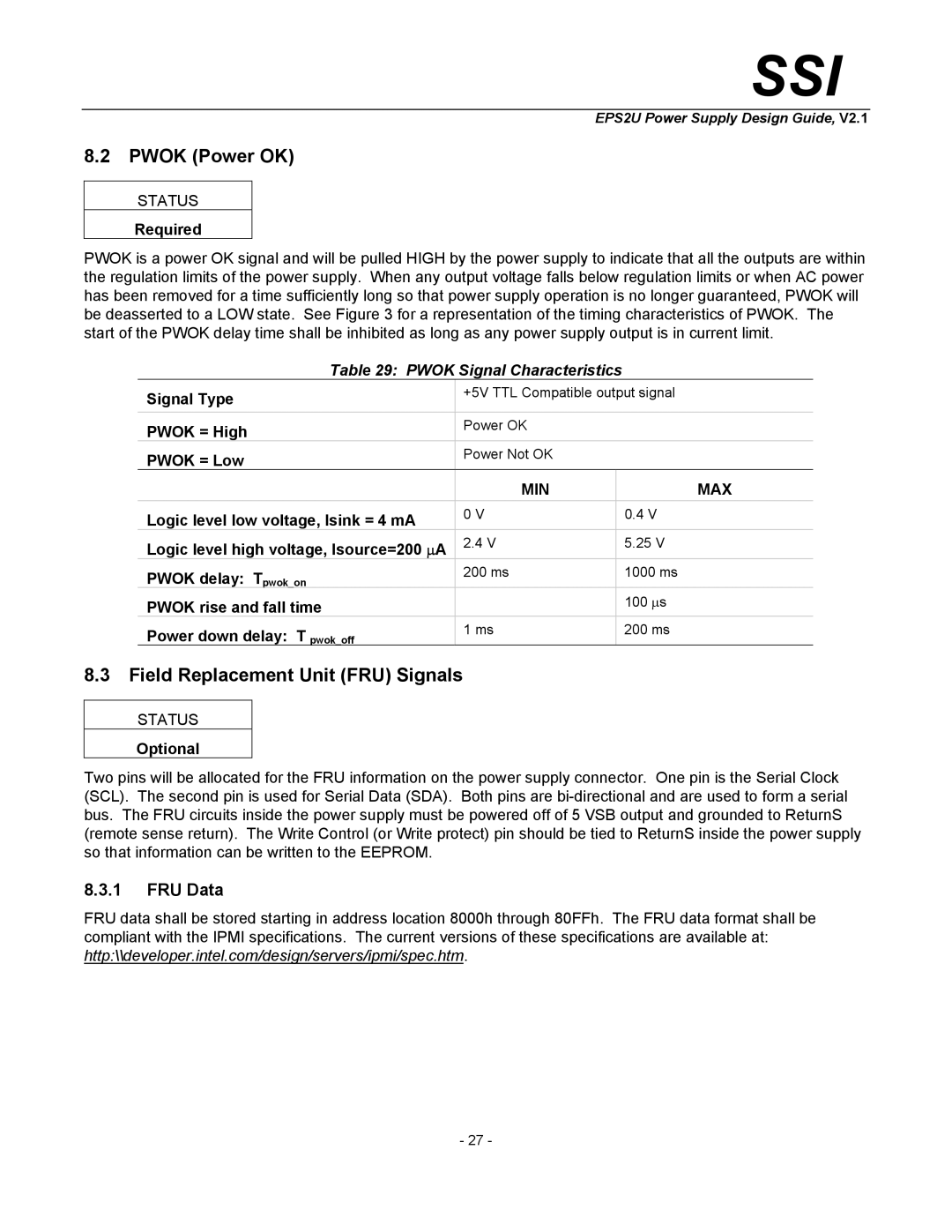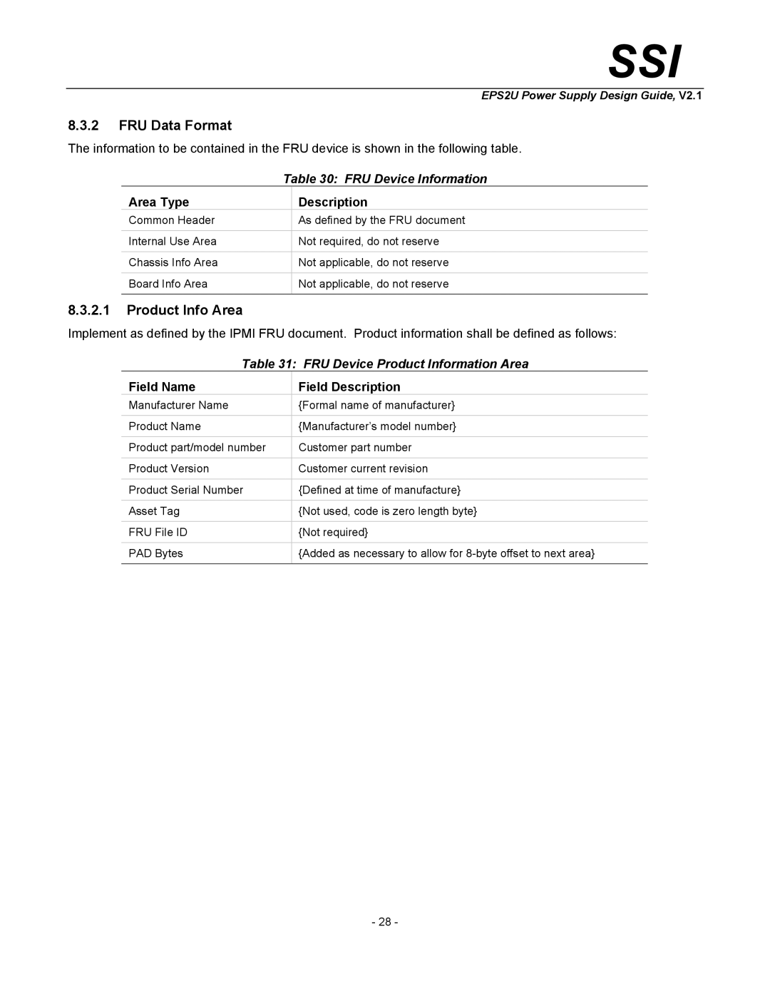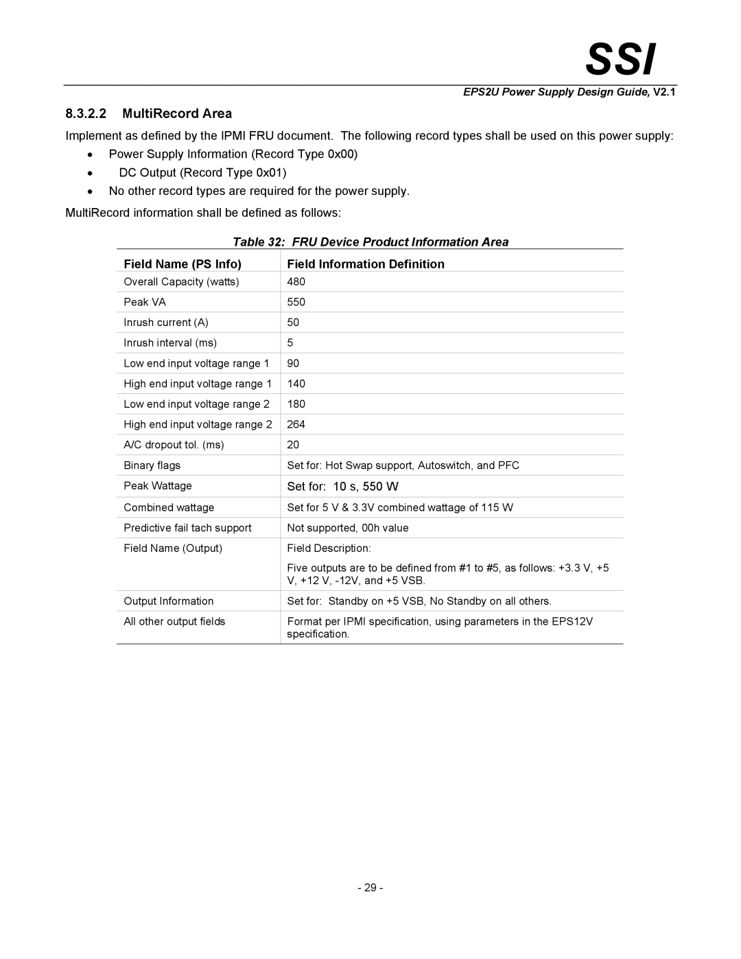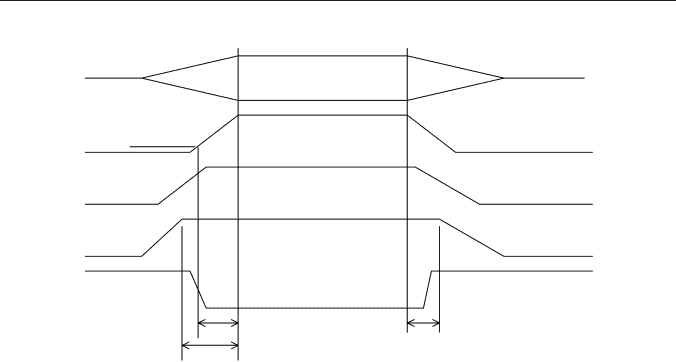
SSI America EPS2U manual Output Voltage Timing Turn On/Off Timing

Page 22

SSI

EPS2U Power Supply Design Guide, V2.1

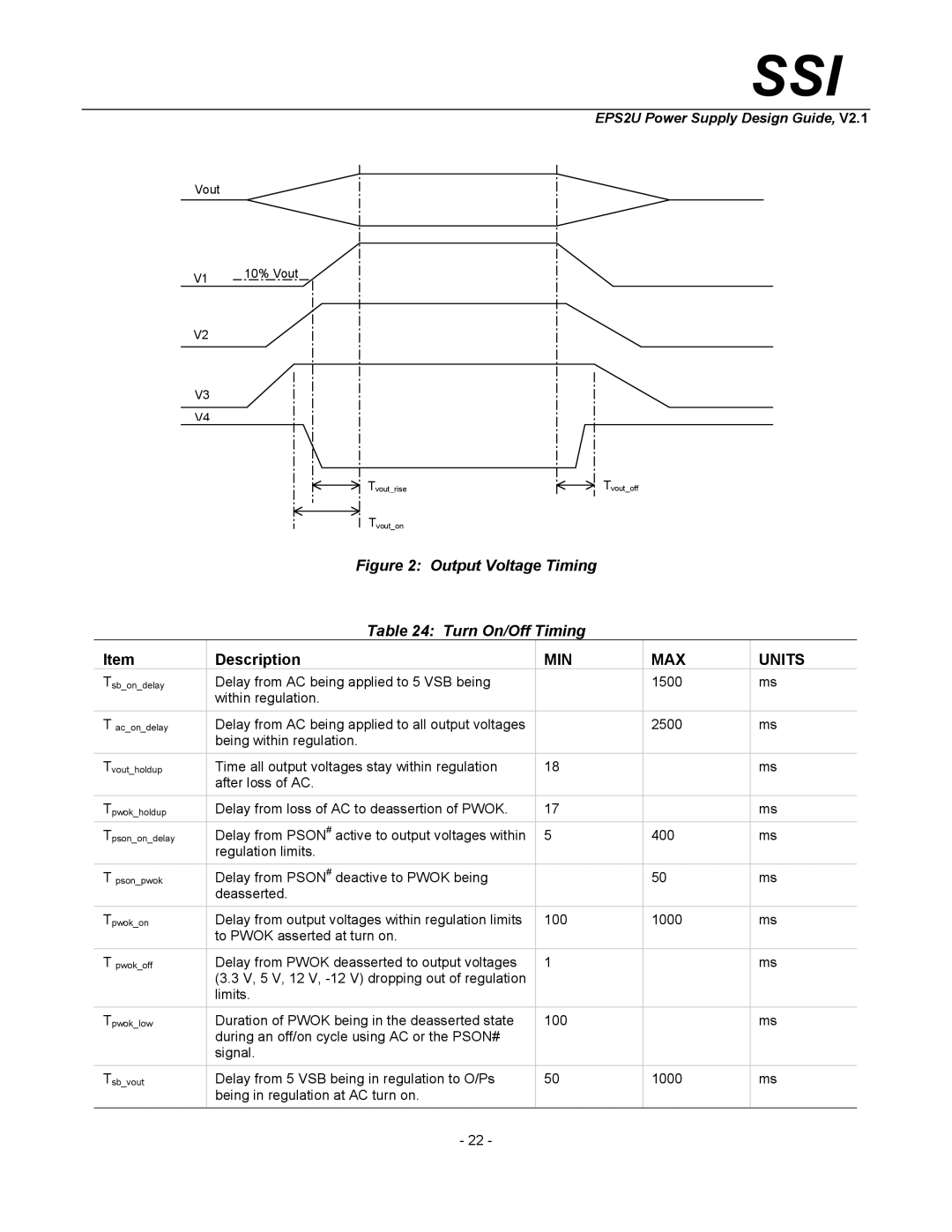
Vout


V1

10% Vout


V2


V3


V4


Tvout_rise


Tvout_off


Tvout_on


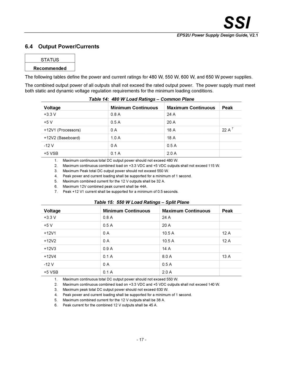
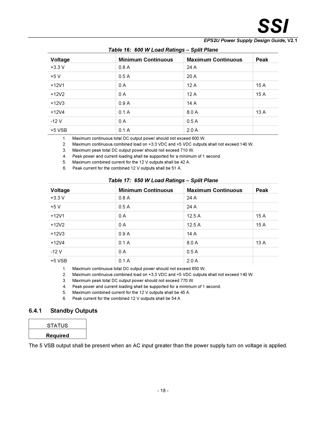
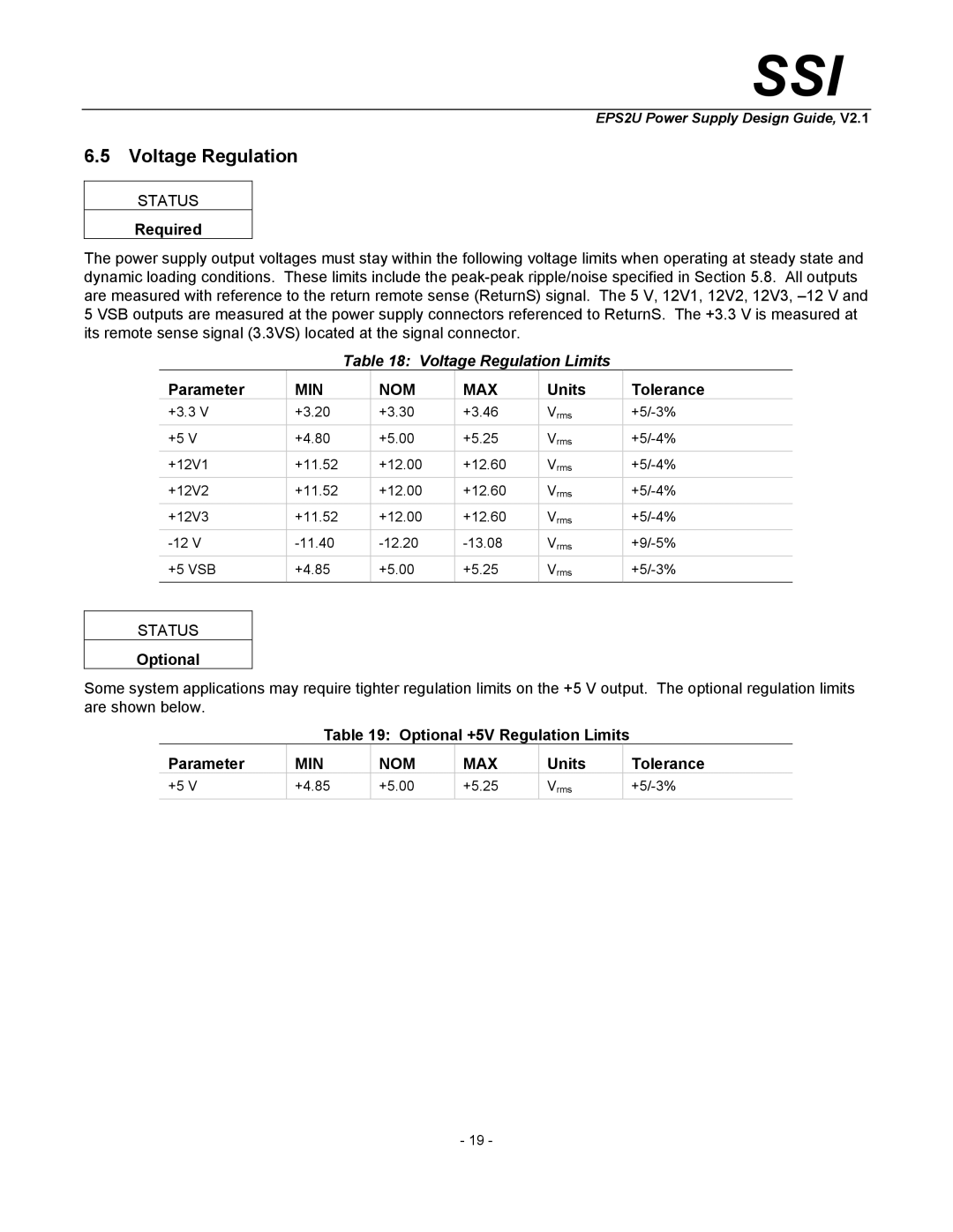
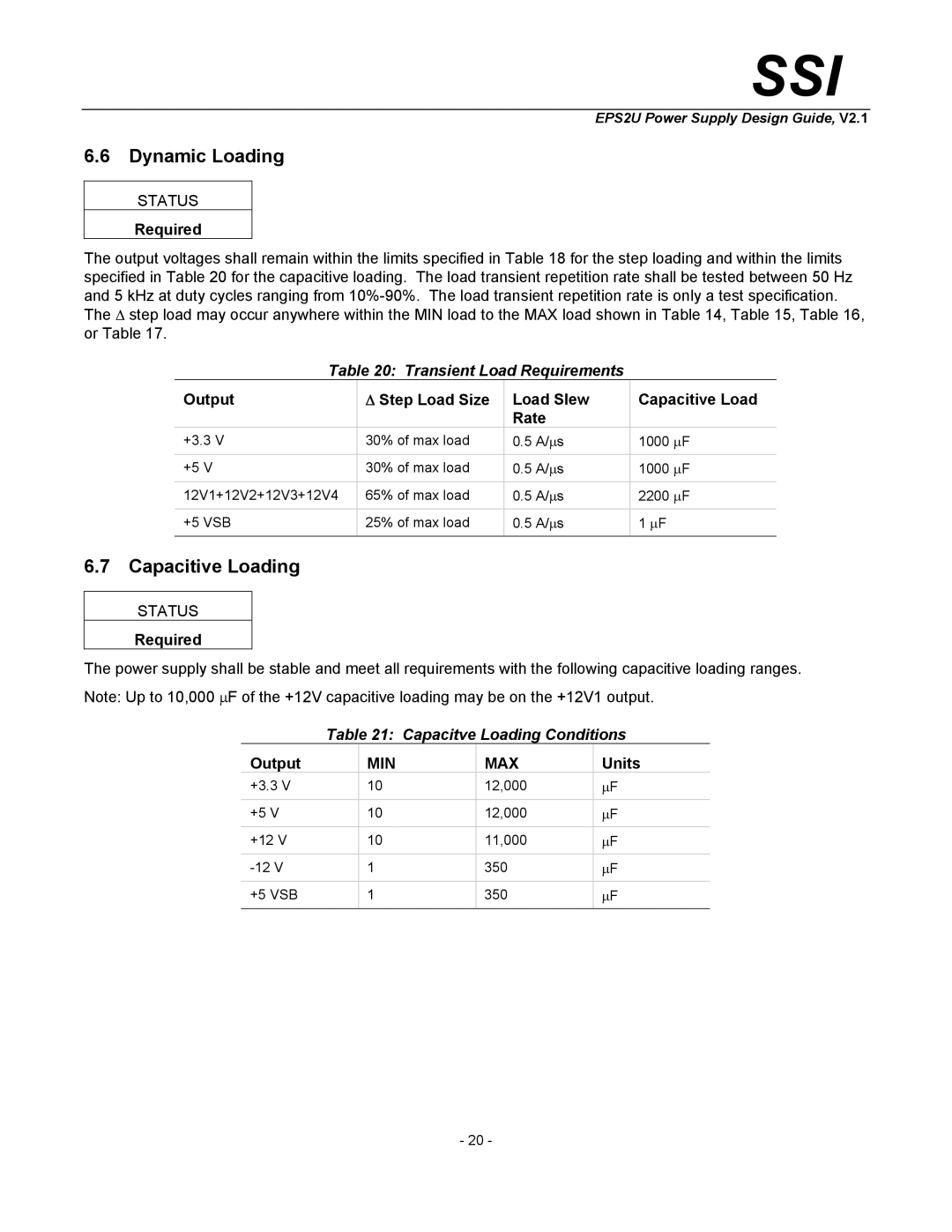
Figure 2: Output Voltage Timing


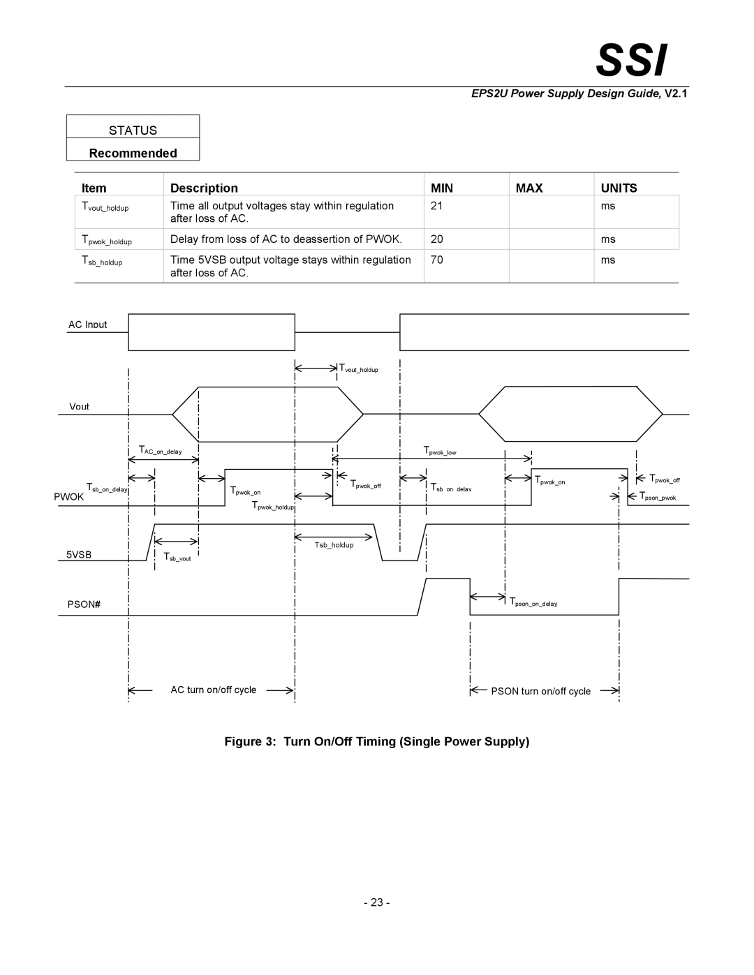
Table 24: Turn On/Off Timing


Item


Description

MIN


MAX

UNITS

Tsb_on_delay


Delay from AC being applied to 5 VSB being


1500

ms


within regulation.


T ac_on_delay


Delay from AC being applied to all output voltages


2500

ms


being within regulation.


Tvout_holdup


Time all output voltages stay within regulation

18


ms


after loss of AC.


Tpwok_holdup


Delay from loss of AC to deassertion of PWOK.

17


ms


Tpson_on_delay


Delay from PSON# active to output voltages within

5


400

ms


regulation limits.


T pson_pwok


Delay from PSON# deactive to PWOK being


50

ms


deasserted.


Tpwok_on


Delay from output voltages within regulation limits

100


1000

ms


to PWOK asserted at turn on.


T pwok_off


Delay from PWOK deasserted to output voltages

1


ms


(3.3 V, 5 V, 12 V, -12 V) dropping out of regulation


limits.


Tpwok_low


Duration of PWOK being in the deasserted state

100


ms


during an off/on cycle using AC or the PSON#


signal.


Tsb_vout


Delay from 5 VSB being in regulation to O/Ps

50


1000

ms


being in regulation at AC turn on.


- 22 -


Image 22
Contents SSI Disclaimer Contents Figures TablesPurpose Conceptual OverviewDefinitions/Terms/Acronyms RequiredMechanical Overview Required OptionalRecommended Temperature RequirementsAirflow Requirements Thermal RequirementsAC Input Requirements AC Inlet ConnectorAC Input Voltage Specification EfficiencyAC Line Fuse AC Line Transient SpecificationAC Line Dropout AC InrushAC Line Surge Transient Performance AC Line Fast Transient SpecificationAC Line Sag Transient Performance AC Line Surge1 12V Power Rail Configurations DC Output SpecificationOutput Connectors 12V Rail SummaryPin Signal AWG Color Baseboard power connectorP1 Baseboard Power Connector Common Plane P1 Baseboard Power Connector Split PlaneProcessor Power Connector Common Plane Processor Power ConnectorProcessor Power Connector Split Plane Server Signal Connector Peripheral Power ConnectorsFloppy Power Connector Peripheral Power ConnectorsGrounding Server Signal ConnectorRemote Sense Voltage Minimum Continuous Maximum Continuous Peak Output Power/Currents480 W Load Ratings Common Plane 550 W Load Ratings Split Plane600 W Load Ratings Split Plane Standby Outputs650 W Load Ratings Split Plane Parameter Voltage RegulationVoltage Regulation Limits Units ToleranceTransient Load Requirements Dynamic LoadingCapacitive Loading Capacitve Loading ConditionsRipple and Noise Ripple / NoiseTiming Requirements Output Voltage TimingOutput Voltage Timing Turn On/Off Timing Turn On/Off Timing Single Power Supply Recommended Description240VA Protection Protection CircuitsCurrent Limit Over Current ProtectionOver Voltage Limits Over Temperature ProtectionOver Voltage Protection Output VoltagePwok delay Control and Indicator FunctionsPson # Signal Characteristic Signal Type PSON#Pwok Signal Characteristics Pwok Power OKField Replacement Unit FRU Signals FRU DataFRU Device Information FRU Data FormatProduct Info Area FRU Device Product Information AreaMultiRecord Area Field Name PS Info Field Information DefinitionMtbf Agency Requirements