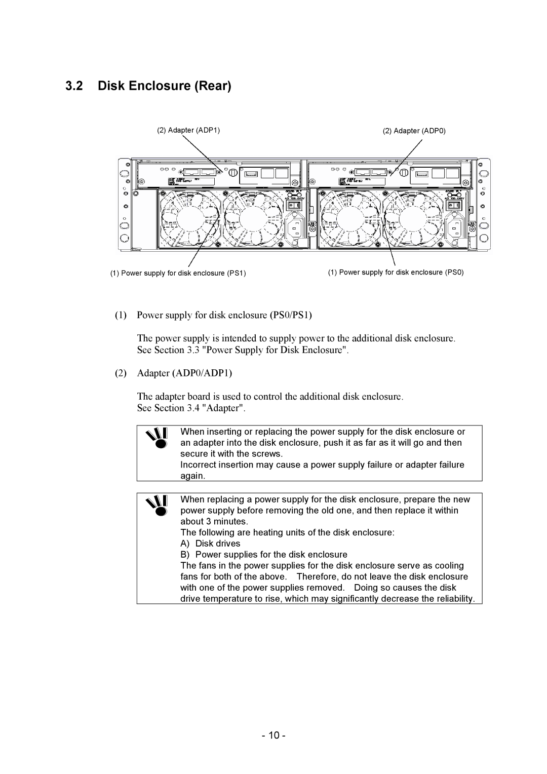
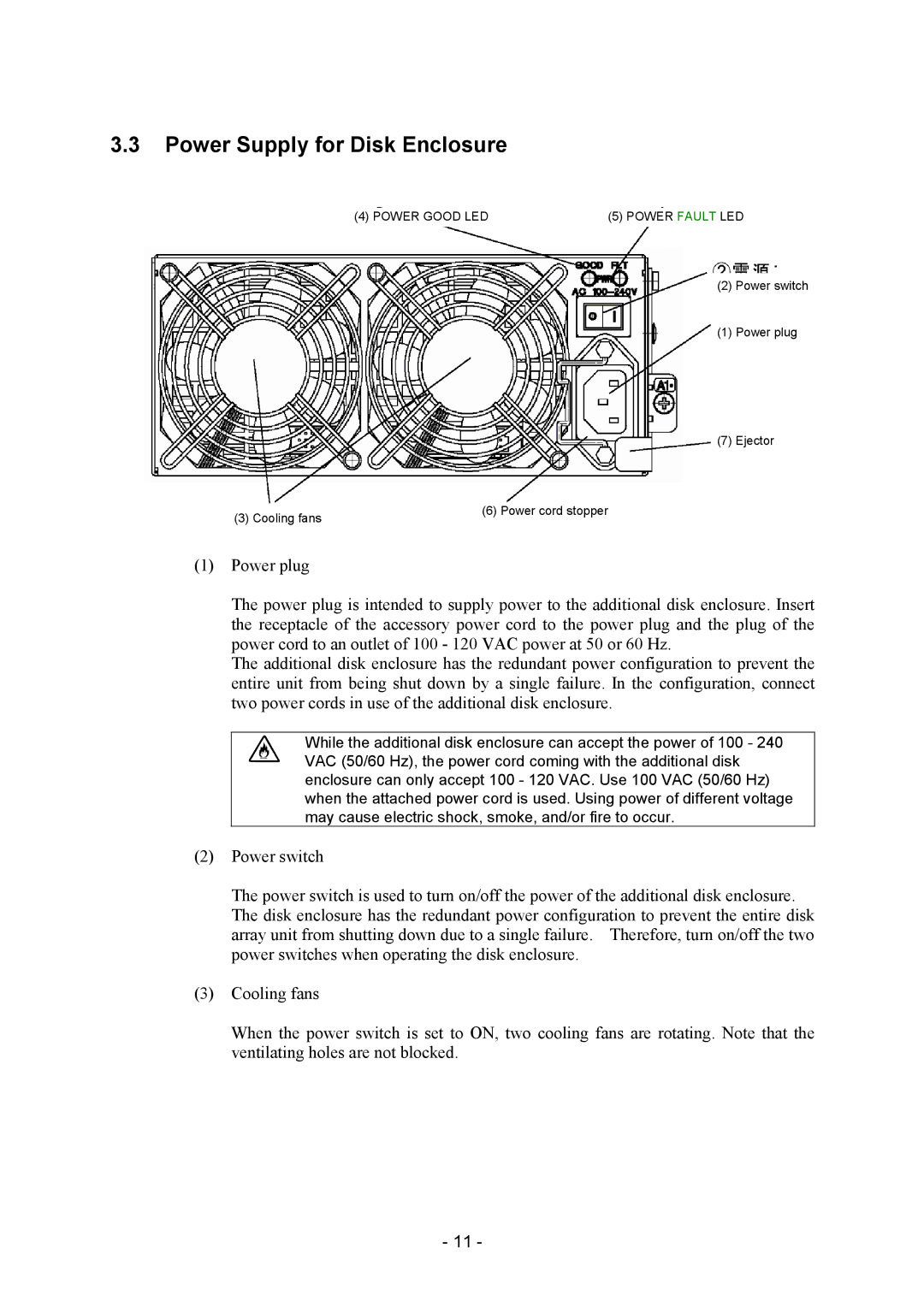
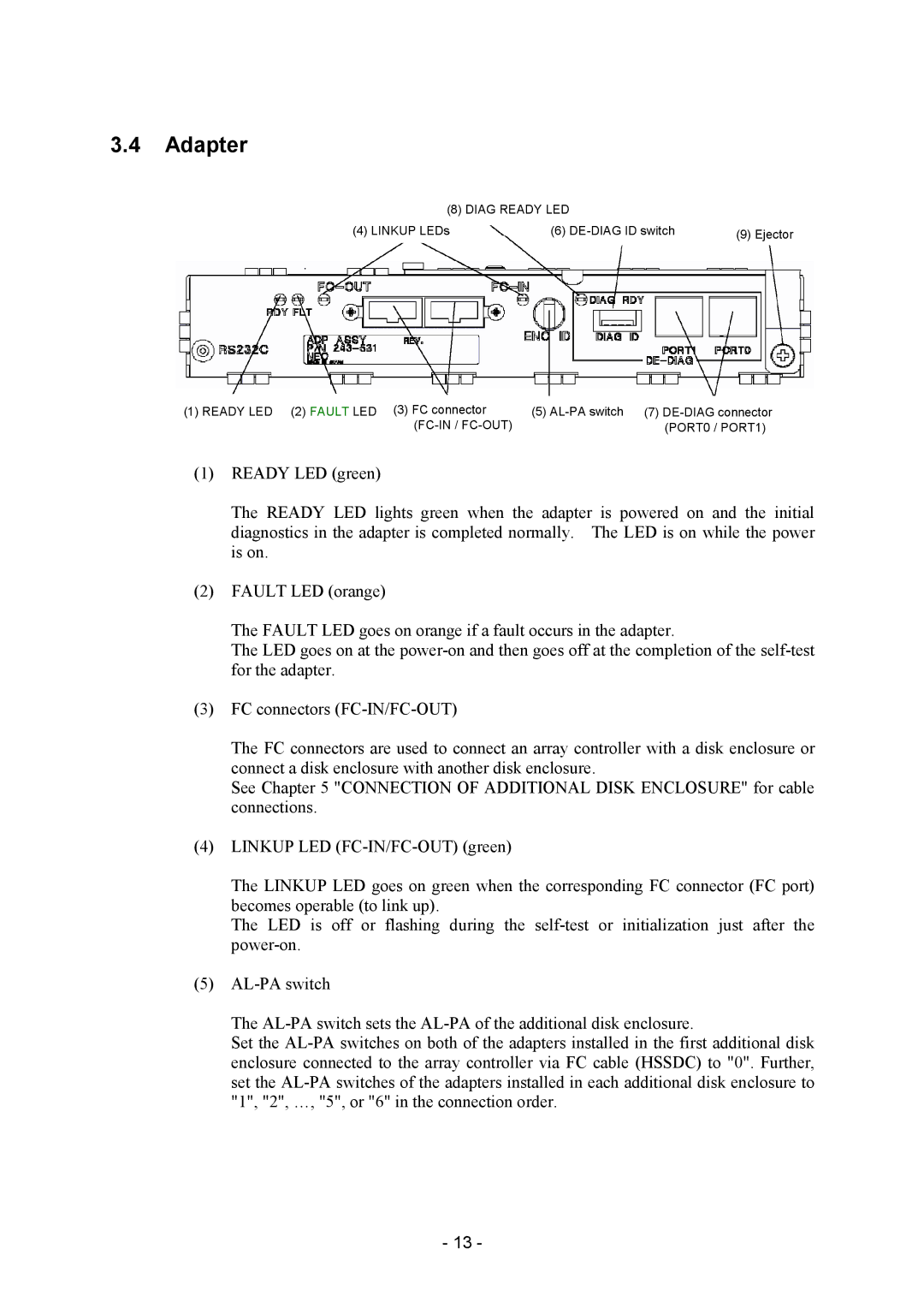
NEC NF2300-SE41E manual Names and Roles of Sections, Disk Enclosure Front

Page 22

3.NAMES AND ROLES OF SECTIONS

This chapter describes the names and functions of the sections in the additional disk enclosure.

3.1Disk Enclosure (Front)

(1) POWER LED


(2) SERVICE LED


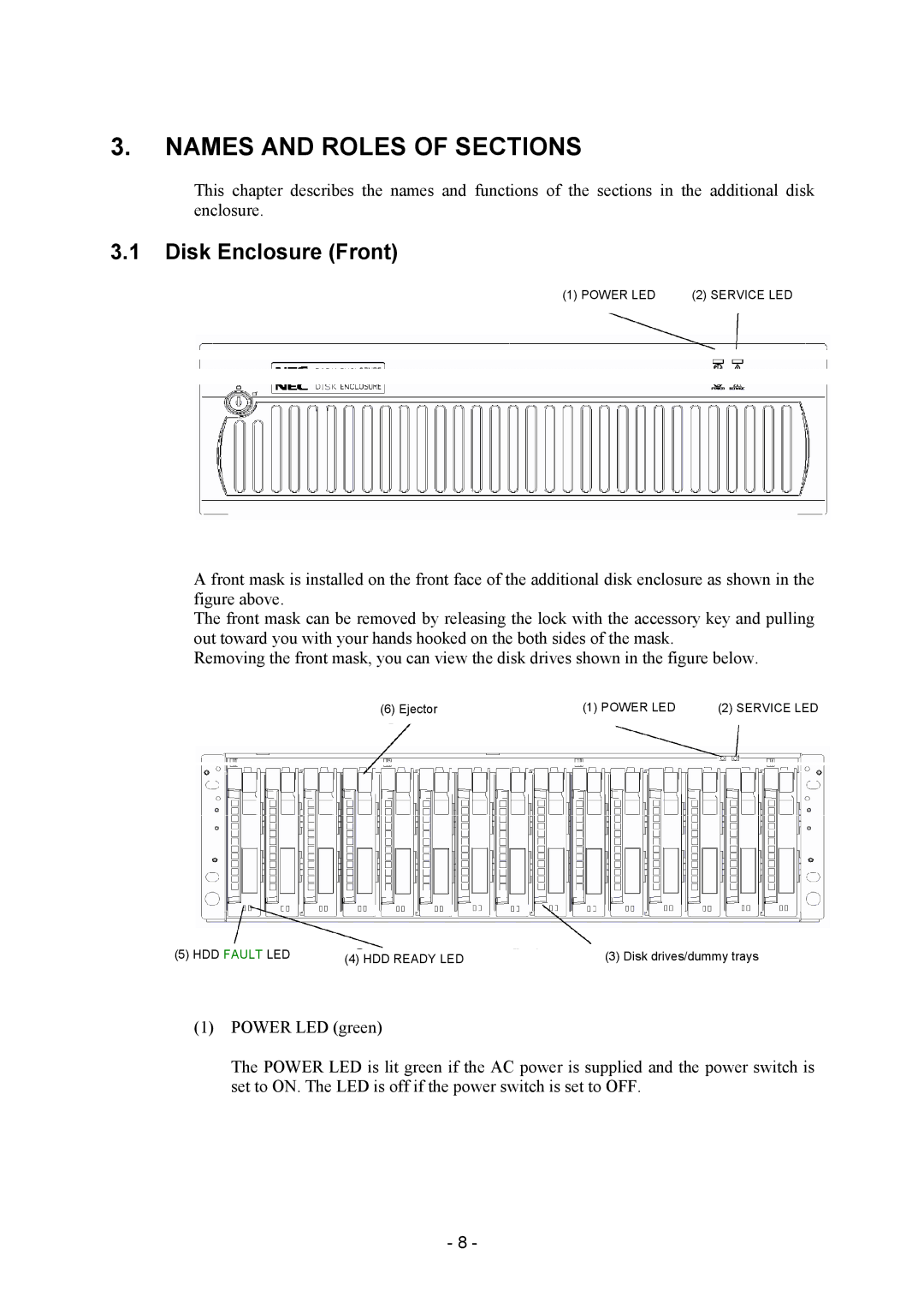
A front mask is installed on the front face of the additional disk enclosure as shown in the figure above.

The front mask can be removed by releasing the lock with the accessory key and pulling out toward you with your hands hooked on the both sides of the mask.

Removing the front mask, you can view the disk drives shown in the figure below.

(6) Ejector


(1) POWER LED


(2) SERVICE LED


(5) HDD FAULT LED

(4) HDD READY LED

(3) Disk drives/dummy trays


(1)POWER LED (green)

The POWER LED is lit green if the AC power is supplied and the power switch is set to ON. The LED is off if the power switch is set to OFF.

-8 -
Image 22
Contents NF2300-SE41E Additional Disk Enclosure Users Guide Page Safety Precautions Page Iii Indication on Safety Page Trademarks Preface Check of Components in Package NF2300-SE41E This Users Guide also uses the following symbol Contents Action Taken AT Occurrence of Fault or Error Page Environment in Use of Additional Disk Enclosure Installation and Connection of Additional Disk Enclosure Page Page Routine Inspection of Additional Disk Enclosure Features of Additional Disk Enclosure Names and Roles of Sections Disk Enclosure FrontPage Disk Enclosure Rear Power Supply for Disk Enclosure Page Adapter Diag Ready LEDPage Installation and Connection Procedures Installation and Connection ProceduresConnection of Additional Disk Enclosure Page Connection of Additional Disk Enclosure OFF Page Page 2 1 on When DE-DIAG ID = 0 When DE-DIAG ID = Sample configuration 1 NF2300-SR4xxE Sample configuration 2 NF2300-SR4xxE + NF2300-SP02E Connection of Power Cords Page Addition of Optional Devices Addition of Disk DriveInstallation procedure Page Page Location 00 in NF2300-SE41E Handling of Additional Disk Enclosure Power On/Off of Additional Disk Enclosure Power switches of disk enclosures Page Page Page Switches of array controller are turned off LD Logical Disk Setting Procedure Spare Disk Setting ProcedureAction Taken AT Occurrence of Fault or Error Additional Disk Enclosure Connection of Additional Disk Indication at Occurrence of Fault Fault of Disk Drive Location label Page Fault of Power Supply for Disk Enclosure Page Page Page Fault of Adapter Be careful that it is hotPage Page Check of Type Name and Manufacturing Numbers Preparation before Phone Call Service and SupportUnit Life/Repair Service Period Disposal of Additional Disk EnclosureOptional Components Product SpecificationBasic Specification of Additional Disk Enclosure Environmental Conditions of Additional Disk EnclosurePower Specification External Dimension and Weight of Additional Disk Enclosure