Return to Section TOC
Return to Section TOC
Return to Section TOC
Return to Section TOC
Return to Master TOC
Return to Master TOC
Return to Master TOC
Return to Master TOC
TROUBLESHOOTING & REPAIR
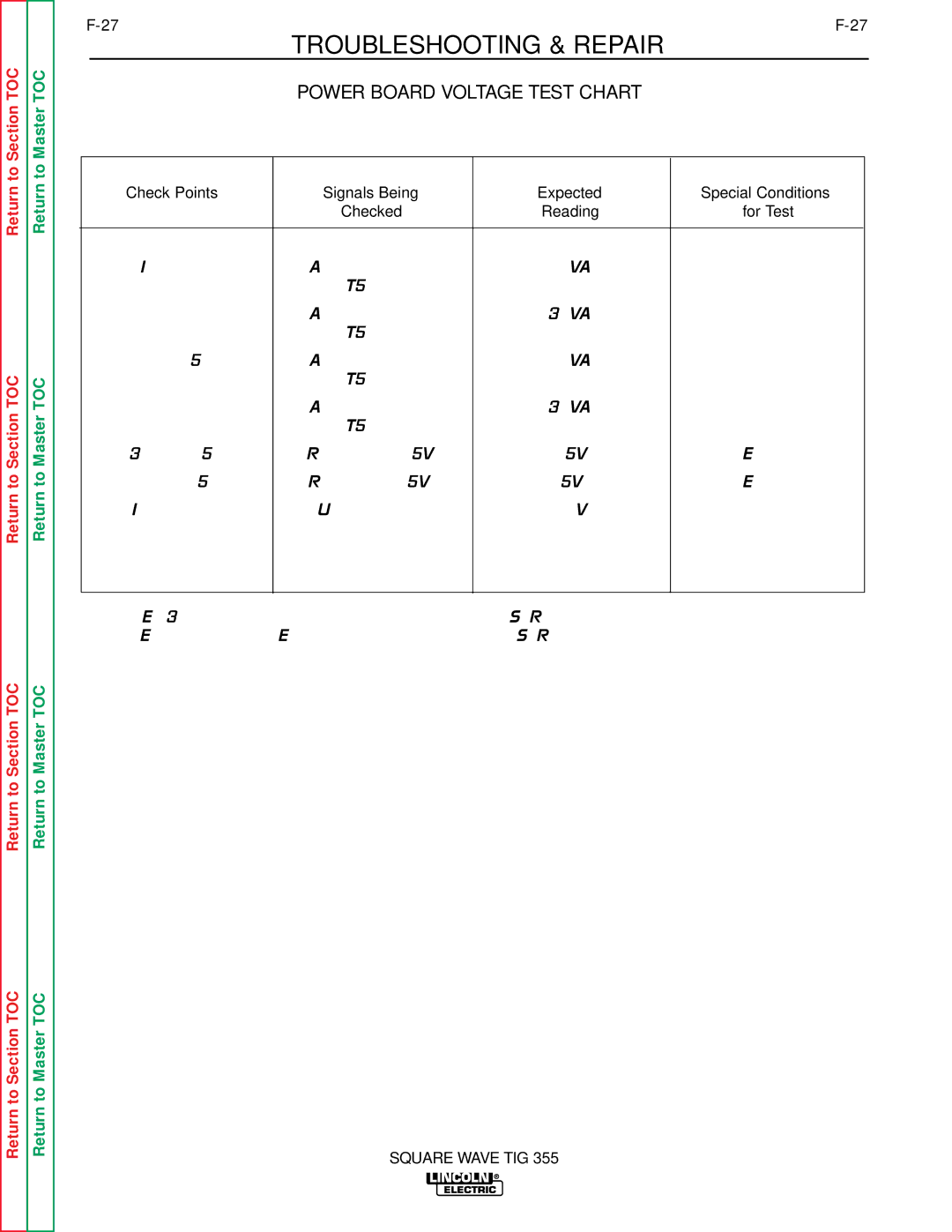
POWER BOARD VOLTAGE TEST CHART
Check Points | Signals Being | Expected | Special Conditions |
| Checked | Reading | for Test |
|
|
|
|
IJ4 to 2J4 | AC supply voltage | 10VAC | None |
| from T5 transformer |
|
|
4J4 to 6J4 | AC supply voltage | 32VAC | None |
| from T5 transformer |
|
|
4J4 to 5J4 | AC supply voltage | 16VAC | None |
| from T5 transformer |
|
|
10J4 to 12J4 | AC supply voltage | 36VAC | None |
| from T5 transformer |
|
|
3J2(+) to 5J2 | Regulated +15VDC | +15VDC | LED 1 ON |
Regulated | LED 2 ON | ||
IJ2(+) to 2J2 | Unregulated DC | +14VDC | None |
|
|
|
|
Note: LED 3 should be ON when gate signal is applied to SCR 1.
LED 4 should be ONE when gate signal is applied to SCR 4.
SQUARE WAVE TIG 355