Section TOC
Master TOC
TROUBLESHOOTING & REPAIR
MAIN TRANSFORMER TEST (continued)
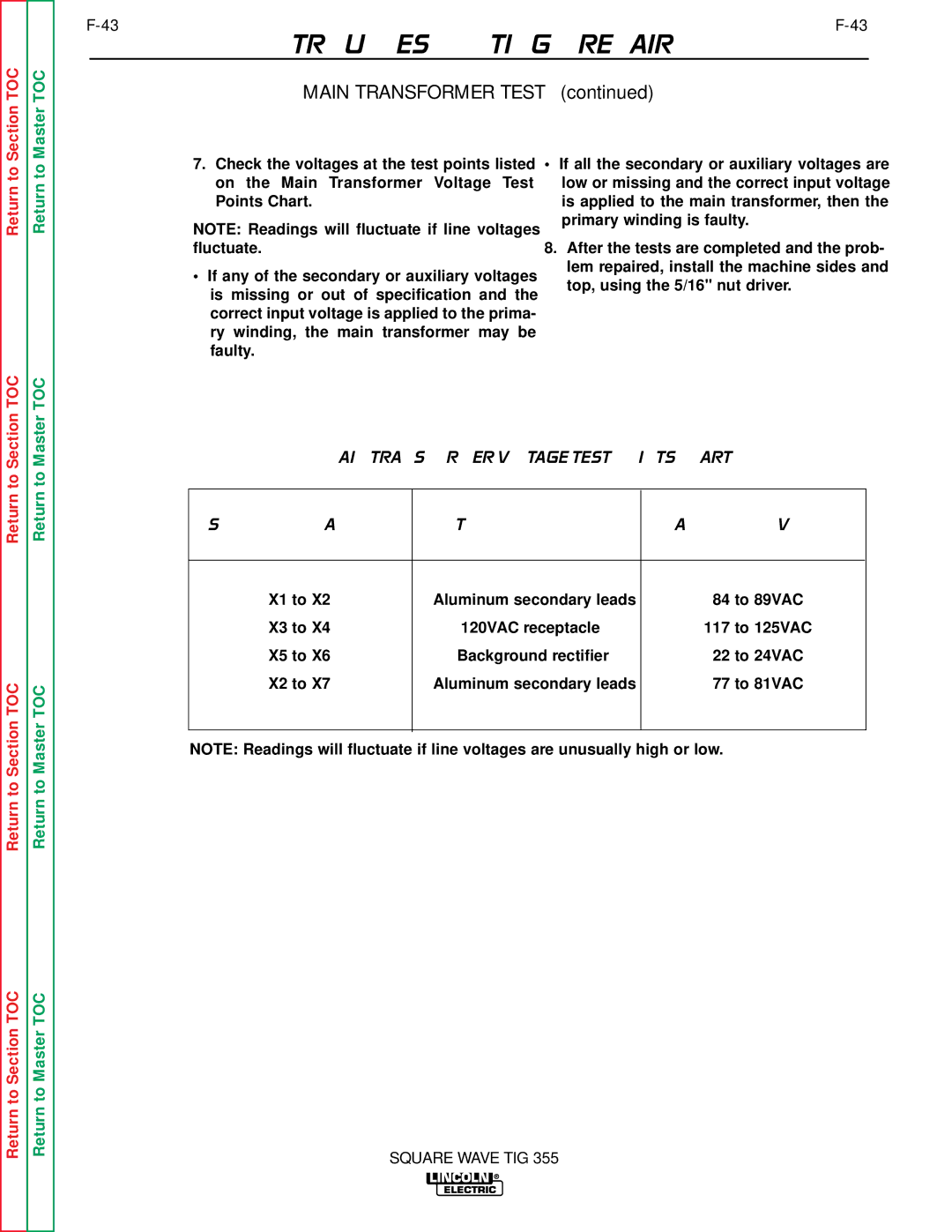
7.Check the voltages at the test points listed on the Main Transformer Voltage Test Points Chart.
NOTE: Readings will fluctuate if line voltages fluctuate.
•If any of the secondary or auxiliary voltages is missing or out of specification and the correct input voltage is applied to the prima- ry winding, the main transformer may be faulty.
•If all the secondary or auxiliary voltages are low or missing and the correct input voltage is applied to the main transformer, then the primary winding is faulty.
8.After the tests are completed and the prob- lem repaired, install the machine sides and top, using the 5/16" nut driver.
Return to Section TOC
Return to Section TOC
Return to Section TOC
Return to Master TOC
Return to Master TOC
Return to Master TOC
MAIN TRANSFORMER VOLTAGE TEST POINTS CHART
Secondary and Auxiliary | Test Point Location | Approximate Voltages |
Leads |
|
|
|
|
|
X1 to X2 | Aluminum secondary leads | 84 to 89VAC |
X3 to X4 | 120VAC receptacle | 117 to 125VAC |
X5 to X6 | Background rectifier | 22 to 24VAC |
X2 to X7 | Aluminum secondary leads | 77 to 81VAC |
|
|
|
NOTE: Readings will fluctuate if line voltages are unusually high or low.
SQUARE WAVE TIG 355