Lincoln Electric SVM118-A service manual Silicon Controlled Rectifier Test, Battery Test

Models: SVM118-A

1 149
Download 149 pages 43.8 Kb
Page 106
Image 106

Return to Section TOC

Return to Master TOC

F-57

F-57

TROUBLESHOOTING & REPAIR

ACTIVE SCR TEST (continued)

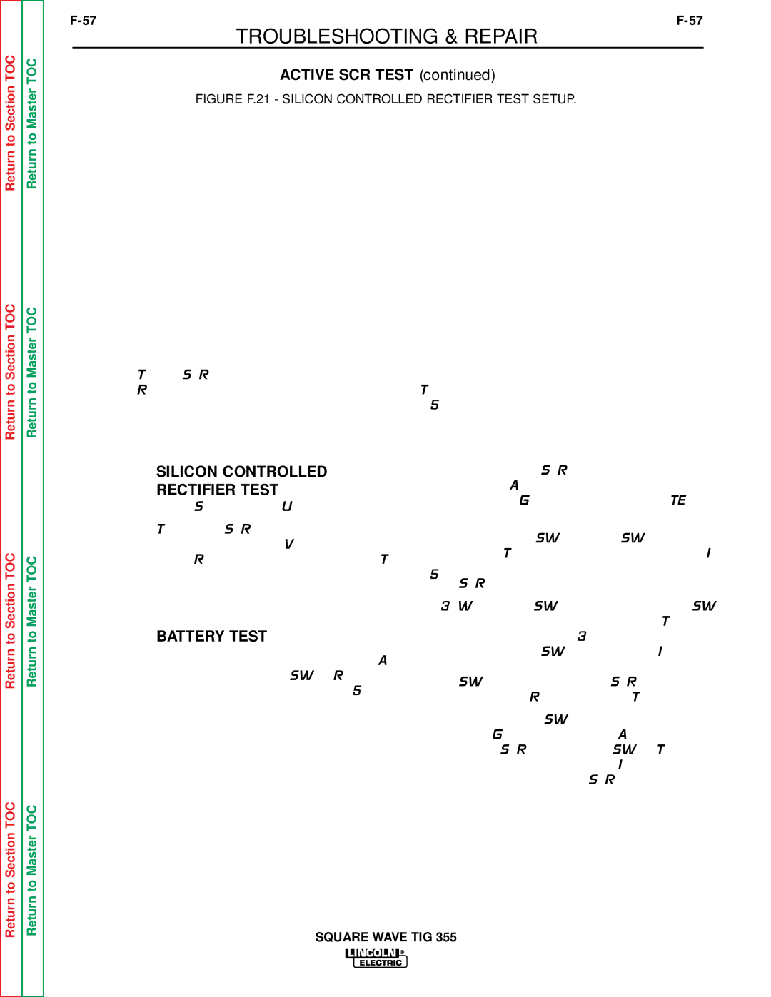
FIGURE F.21 - SILICON CONTROLLED RECTIFIER TEST SETUP.

Return to Section TOC

Return to Section TOC

Return to Master TOC

Return to Master TOC

To test SCRs construct the circuit outlined above. Resistor values are plus or minus ten percent. The voltmeter scale should be low, approximately 0-5 or 0-10 volts DC.

SILICON CONTROLLED

RECTIFIER TEST

(Heat Sink Mounted Units)

To test the SCRs, construct the circuit outlined in Figure F.21. One 6V lantern battery can be used. Resistor tolerances are 10%. The volt- meter scale should be low, approximately 0-5 or 0-10 volts.

BATTERY TEST

Check the battery by shorting leads (A) and (C) and then close switch SW-1. Replace the bat- tery if the voltage is less than 4.5 volts.

1.Connect the SCR into the test circuit as shown: (A) lead to anode, (C) lead to cath- ode, and (G) lead to the gate. NOTE: the gate leads are located in plug J1.

2.Close switch SW-1 (switch SW-2 should be open). The voltmeter should read zero. If the voltmeter reads higher than zero, the SCR is shorted.

3.With switch SW-1 closed, close switch SW- 2 for two seconds and release. The volt- meter should read 3 to 6 volts before and after switch SW-2 is released. If the volt- meter does not read, or reads only while SW-2 is depressed, the SCR or battery is defective. (Repeat Battery Test Procedure)

4.Open switch SW-1, disconnect the gate lead (G), and reverse the (A) and (C) leads on the SCR. Close switch SW-1. The volt- meter should read zero. If the voltage is higher than zero, the SCR is shorted.

Return to Section TOC

Return to Master TOC

SQUARE WAVE TIG 355

Page 106
Image 106
Lincoln Electric SVM118-A service manual Silicon Controlled Rectifier Test, Battery Test