Return to Section TOC
Return to Section TOC
Return to Section TOC
Return to Section TOC
Return to Master TOC
Return to Master TOC
Return to Master TOC
Return to Master TOC
THEORY OF OPERATION
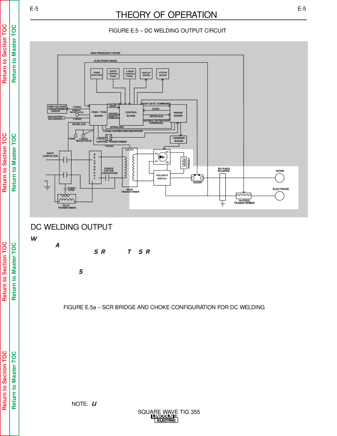
FIGURE E.5 – DC WELDING OUTPUT CIRCUIT
HIGH FREQUENCY SPARK
ELECTRODE SENSE
PANEL | UPPER |
|
| LOWER |
| DISPLAY |
| STATUS | |
CONTROL |
| CONTROL |
|
| |||||
SWITCHES |
|
| BOARD |
| BOARD | ||||
PANEL |
|
| PANEL |
|
| ||||
|
|
|
|
|
|
| |||
|
|
|
|
|
|
|
|
|
|
|
|
|
|
|
|
|
|
|
|
|
|
| ELECTRODE |
| SCR GATE COMMANDS |
|
HIGH VOLTAGE | 115VAC |
| SENSE |
| 15VDC |
|
TRANSFORMER | REMOTE |
|
|
|
| |
CIRCUIT | FEED - THRU | CONTROL |
| POWER | ||
| RECEPTACLE |
| ||||
|
| BOARD | TRIGGER | BOARD |
| BOARD |
GAS/WATER |
| REMOTE | INTERLOCK | |||
SOLENOIDS | 115VAC |
| COMMANDS |
|
|
|
|
|
|
| |||
|
|
|
|
|
| |
| INTERLOCK |
|
|
| COMMANDS |
|
|
|
|
|
|
| |
|
|
| INTERLOCK |
|
|
|
|
|
| 115VAC |
|
| |
| FANS 115VAC | 115VAC |
|
| SNUBBER | |
| RECEPTACLE | CONTROL TRANSFORMER |
| BOARD | ||
|
|
| 115VAC |
|
|
|
INPUT | R |
| AC | DC- |
|
|
|
|
|
|
|
| |||
CONTACTOR |
|
|
|
|
|
| |
E |
|
|
|
|
|
| |
|
|
|
| C |
|
| |
| C |
|
|
|
|
| |
|
| AC | DC+ | H |
|
| |
| O |
|
| O |
|
| |
| N |
|
|
| K |
|
|
| POWER |
|
| E |
| ||
| N |
|
|
| WORK | ||
| E | FACTOR |
|
|
| BOARDS | |
| CAPACITORS | POLARITY |
|
|
| ||
| C |
|
|
|
| ||
| T |
| SWITCH |
|
|
| |
|
|
|
|
|
| SHUNT |
|
| START/ | MAIN |
|
|
|
| ELECTRODE |
| STOP |
|
|
|
| ||
|
| TRANSFORMER |
|
|
|
|
|
|
|
|
|
|
|
| |
| PILOT |
|
|
|
|
| TRANSFORMER |
|
|
|
|
|
|
| |
| TRANSFORMER |
|
|
|
|
|
|
DC WELDING OUTPUT
When the polarity switch is placed in either DC posi- tion, the AC voltage from the main transformer sec- ondary is applied to the SCR bridge. The SCR bridge and choke circuits are connected in a conventional full wave bridge and filter configuration, resulting in a con- trolled DC output. Since the choke is in series with the negative leg of the bridge and also in series with the welding load, a filtered DC is applied to the machine output terminals.
FIGURE E.5a – SCR BRIDGE AND CHOKE CONFIGURATION FOR DC WELDING
NOTE: Unshaded areas of Block Logic Diagram are the subject of discussion.
SQUARE WAVE TIG 355