TROUBLESHOOTING & REPAIR
TOC | TOC |
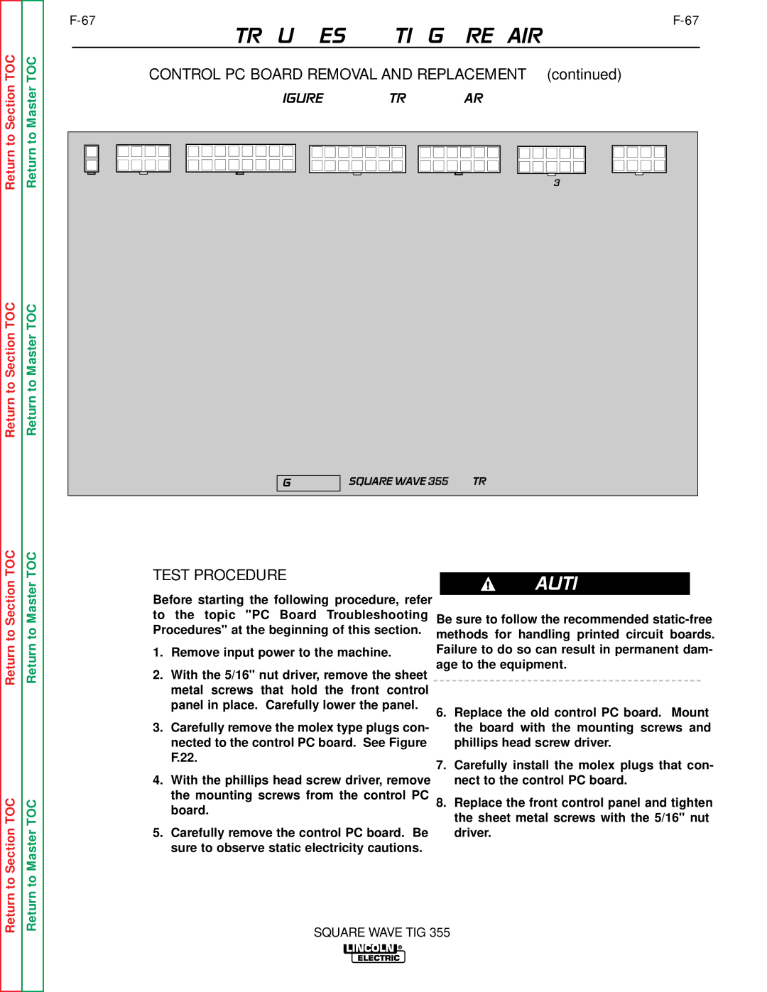
| CONTROL PC BOARD REMOVAL AND REPLACEMENT (continued) |
| ||||
to Section | to Master |
|
| FIGURE F.22 - CONTROL PC BOARD |
|
| ||
|
|
|
|
|
|
| ||
Return | Return | J8 | J9 | J10 | J11 | J12 | J13 | J14 |
|
|
|
|
|
|
| ||
Return to Section TOC | Return to Master TOC |
|
|
|
|
|
|
|
|
|
|
| SQUARE WAVE 355 CONTROL |
|
| ||
TOC | TOC | TEST PROCEDURE |
|
|
|
| ||
|
| CAUTION |
| |||||
Section | Master | Before starting the following procedure, refer |
|
|
| |||
|
|
|
|
|
| |||
|
| to | the topic "PC Board Troubleshooting | Be sure to follow the recommended | ||||
|
| Procedures" at the beginning of this section. | ||||||
to | to | methods for handling printed circuit boards. | ||||||
|
| |||||||
|
| Failure to do so can result in permanent dam- | ||||||
Return | Return | 1. | Remove input power to the machine. | |||||
2. With the 5/16" nut driver, remove the sheet | age to the equipment. | |||||||
|
| |||||||
|
|
|
|
|
| |||
|
|
| metal screws that hold the front control |
|
|
|
| |
|
|
| panel in place. Carefully lower the panel. | 6. Replace the old control PC board. Mount | ||||
|
|
|
| |||||
|
| 3. Carefully remove the molex type plugs con- |
| the board with the mounting screws and | ||||
|
|
| nected to the control PC board. See Figure |
| phillips head screw driver. | |||
|
|
| F.22. | 7. Carefully install the molex plugs that con- | ||||
|
|
|
| |||||
|
| 4. | With the phillips head screw driver, remove |
| nect to the control PC board. | |||
TOC | TOC |
| the mounting screws from the control PC | 8. Replace the front control panel and tighten | ||||
| board. | |||||||
|
| the sheet metal screws with the 5/16" nut | ||||||
|
|
|
| |||||
|
|
|
|
| ||||
SectiontoReturn | MastertoReturn | 5. | Carefully remove the control PC board. Be |
| driver. | |||
| sure to observe static electricity cautions. |
|
|
|
| |||
|
|
|
|
|
|
| ||
|
|
| SQUARE WAVE TIG 355 | |||||