Return to Section TOC
Return to Section TOC
Return to Master TOC
Return to Master TOC
THEORY OF OPERATION
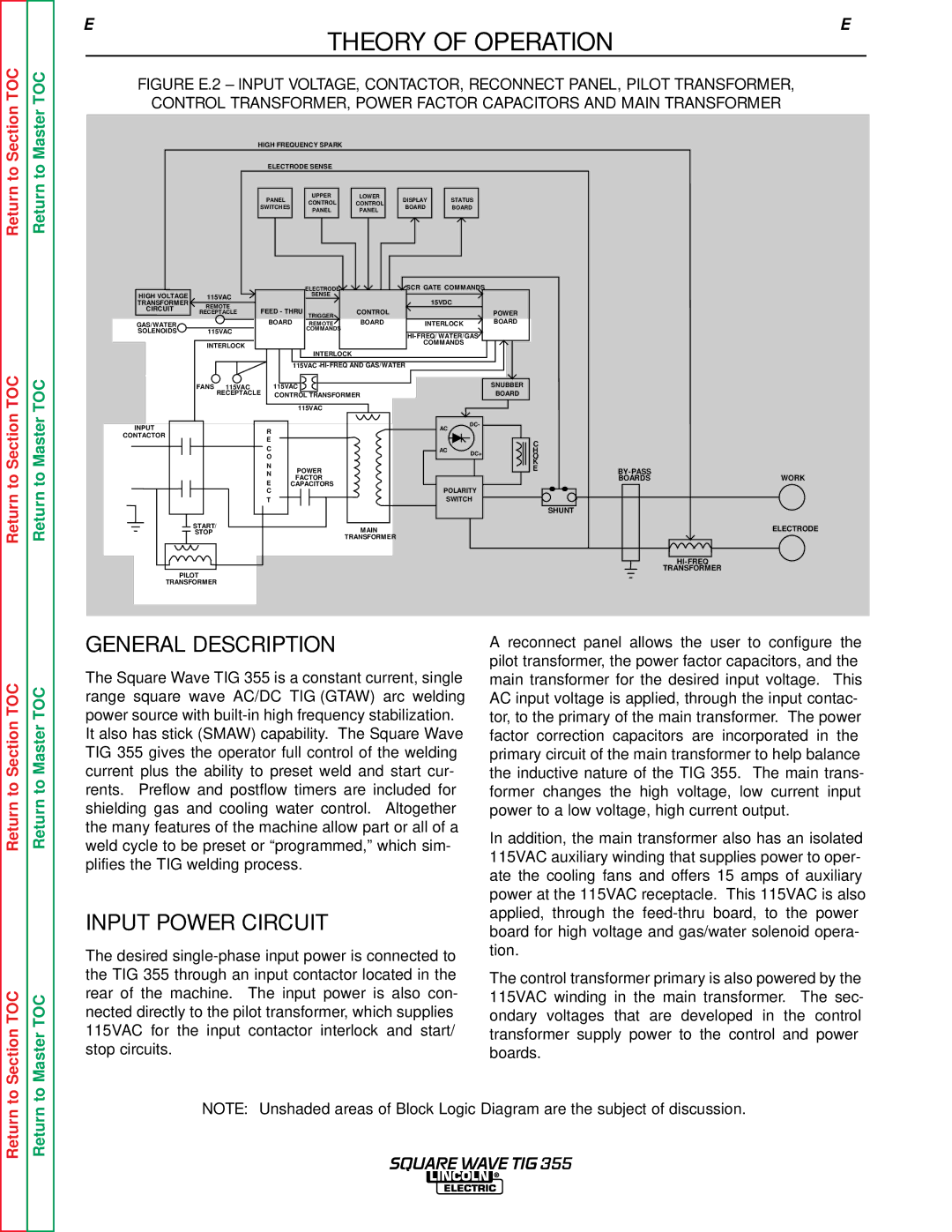
FIGURE E.2 – INPUT VOLTAGE, CONTACTOR, RECONNECT PANEL, PILOT TRANSFORMER, CONTROL TRANSFORMER, POWER FACTOR CAPACITORS AND MAIN TRANSFORMER
HIGH FREQUENCY SPARK
ELECTRODE SENSE
PANEL | UPPER |
|
| LOWER |
| DISPLAY |
| STATUS | |
CONTROL |
| CONTROL |
|
| |||||
SWITCHES |
|
| BOARD |
| BOARD | ||||
PANEL |
|
| PANEL |
|
| ||||
|
|
|
|
|
|
| |||
|
|
|
|
|
|
|
|
|
|
|
|
|
|
|
|
|
|
|
|
|
|
| ELECTRODE |
| SCR GATE COMMANDS |
|
HIGH VOLTAGE | 115VAC |
| SENSE |
| 15VDC |
|
TRANSFORMER | REMOTE |
|
|
|
| |
CIRCUIT | FEED - THRU | CONTROL |
| POWER | ||
| RECEPTACLE |
| ||||
|
| BOARD | TRIGGER | BOARD |
| BOARD |
GAS/WATER |
| REMOTE | INTERLOCK | |||
SOLENOIDS | 115VAC |
| COMMANDS |
|
|
|
|
|
|
| |||
|
|
|
|
|
| |
| INTERLOCK |
|
|
| COMMANDS |
|
|
|
|
|
|
| |
|
|
| INTERLOCK |
|
|
|
|
|
| 115VAC |
|
| |
| FANS 115VAC | 115VAC |
|
| SNUBBER | |
| RECEPTACLE | CONTROL TRANSFORMER |
| BOARD | ||
|
|
| 115VAC |
|
|
|
INPUT | R |
| AC | DC- |
|
|
|
|
|
|
|
| |||
CONTACTOR |
|
|
|
|
|
| |
E |
|
|
|
|
|
| |
|
|
|
| C |
|
| |
| C |
|
|
|
|
| |
|
| AC | DC+ | H |
|
| |
| O |
|
| O |
|
| |
| N |
|
|
| K |
|
|
| POWER |
|
| E |
| ||
| N |
|
|
| WORK | ||
| E | FACTOR |
|
|
| BOARDS | |
| CAPACITORS | POLARITY |
|
|
| ||
| C |
|
|
|
| ||
| T |
| SWITCH |
|
|
| |
|
|
|
|
|
| SHUNT |
|
| START/ | MAIN |
|
|
|
| ELECTRODE |
| STOP |
|
|
|
| ||
|
| TRANSFORMER |
|
|
|
|
|
|
|
|
|
|
|
| |
| PILOT |
|
|
|
|
| TRANSFORMER |
|
|
|
|
|
|
| |
| TRANSFORMER |
|
|
|
|
|
|
Return to Section TOC
to Section TOC
Return to Master TOC
to Master TOC
GENERAL DESCRIPTION
The Square Wave TIG 355 is a constant current, single range square wave AC/DC TIG (GTAW) arc welding power source with
INPUT POWER CIRCUIT
The desired
A reconnect panel allows the user to configure the pilot transformer, the power factor capacitors, and the main transformer for the desired input voltage. This AC input voltage is applied, through the input contac- tor, to the primary of the main transformer. The power factor correction capacitors are incorporated in the primary circuit of the main transformer to help balance the inductive nature of the TIG 355. The main trans- former changes the high voltage, low current input power to a low voltage, high current output.
In addition, the main transformer also has an isolated 115VAC auxiliary winding that supplies power to oper- ate the cooling fans and offers 15 amps of auxiliary power at the 115VAC receptacle. This 115VAC is also applied, through the
The control transformer primary is also powered by the 115VAC winding in the main transformer. The sec- ondary voltages that are developed in the control transformer supply power to the control and power boards.
Return
Return
NOTE: Unshaded areas of Block Logic Diagram are the subject of discussion.
SQUARE WAVE TIG 355