Return to Section TOC
Return to Master TOC
INSTALLATION
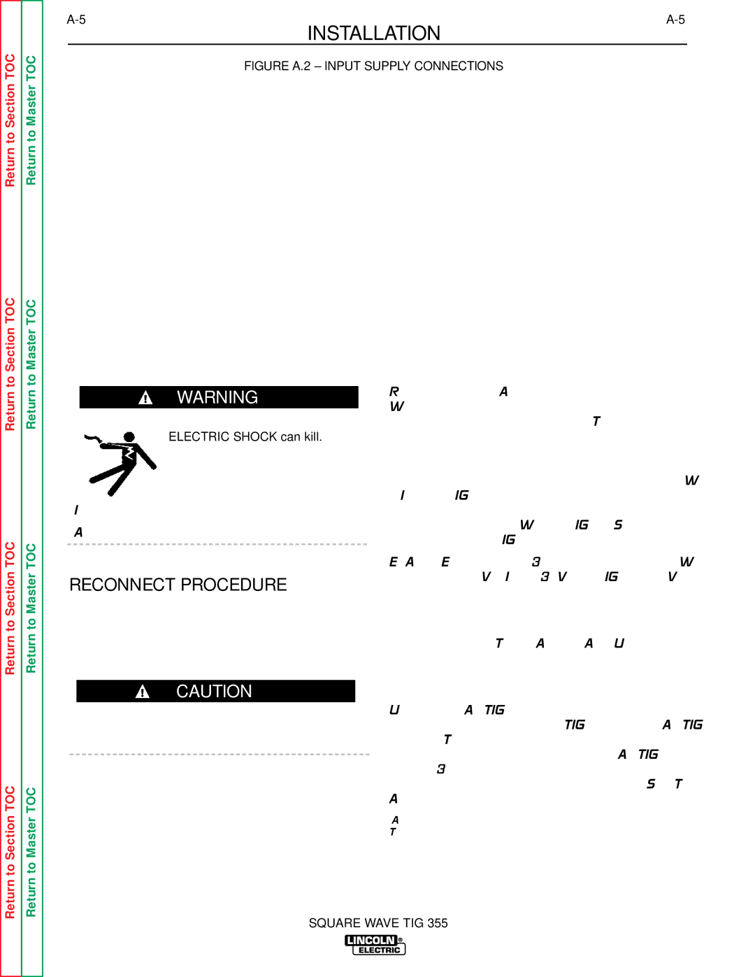
FIGURE A.2 – INPUT SUPPLY CONNECTIONS
Return to Section TOC
Return to Section TOC
Return to Section TOC
Return to Master TOC
Return to Master TOC
Return to Master TOC
WARNING
ELECTRIC SHOCK can kill.
•Do not touch electrically live parts or electrodes with your skin or wet clothing.
•Insulate yourself from the work and ground.
•Always wear dry insulating gloves.
RECONNECT PROCEDURE
On multiple input voltage welders, be sure the recon- nect panel is connected according to the following instructions for the voltage being supplied to the welder.
CAUTION
Failure to follow these instructions can cause immedi- ate failure of components within the welder.
Refer to Figure A.2 for the following procedure. Welders are shipped connected for the highest input voltage listed on the rating plate. To change this con- nection for a different input voltage, reconnect both the power strap (P) and control lead (C) to their respective terminals corresponding to the input volt- age used. Designations on reconnect panel, LOW, MID and HIGH, correspond to the nameplate input voltages of a triple voltage welder. Dual voltage welders use only LOW and HIGH. Single voltage welders use only HIGH.
EXAMPLE: On a 208/230/460 volt welder, LOW is 208V, MID is 230V, and HIGH is 460V.
Fuse the input circuit with the recommended super lag fuses or delay type1 circuit breakers. Choose an input and grounding wire size according to local or national codes or refer to Tables A.1 and A.2. Using fuses or circuit breakers smaller than recommended may result in “nuisance”
Unbalanced AC TIG welding draws higher input cur- rents than those for stick, DC TIG, or Balanced AC TIG welding. The welder is designed for these higher input currents. However, where unbalanced AC TIG welding above 230 amps is planned, the higher input currents require larger input wire sizes and fuses. See Table A.2.
1Also called “inverse time” or “thermal/magnetic” circuit breakers. These circuit breakers have a delay in tripping action that decreases as the magnitude of the current increases.
SQUARE WAVE TIG 355