11. HOW TO REPLACE THE MAIN PARTS
| Indoor Unit |
|
|
|
|
|
|
|
|
|
|
|
|
|
|
|
| ||||
No. | Part name |
| Procedure |
|
| Remarks | ||||
|
|
|
|
|
|
|
|
|
|
|
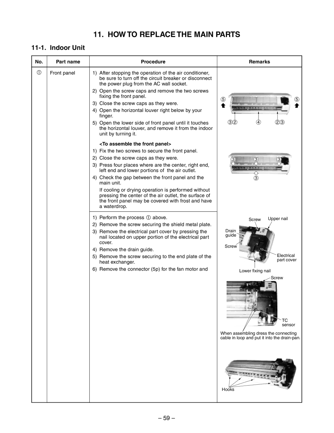
Q | Front panel | 1) | After stopping the operation of the air conditioner, |
|
|
|
|
|
|
|
|
|
| be sure to turn off the circuit breaker or disconnect |
|
|
|
|
|
|
|
|
|
| the power plug from the AC wall socket. |
|
|
|
|
|
|
|
|
| 2) | Open the screw caps and remove the two screws |
|
|
|
|
|
|
|
|
|
| fixing the front panel. |
|
|
|
|
| 5 | |
|
| 3) | 5 |
|
|
|
|
| ||
|
| Close the screw caps as they were. |
|
|
|
|
|
|
| |
|
| 4) | Open the horizontal louver right below by your |
|
|
|
|
|
|
|
|
|
| finger. |
|
|
|
|
|
|
|
|
| 5) | Open the lower side of front panel until it touches | 3 2 | 4 | 2 3 | ||||
|
|
| the horizontal louver, and remove it from the indoor |
|
|
|
|
|
|
|
|
|
| unit by turning it. |
|
|
|
|
|
|
|
|
|
| <To assemble the front panel> |
|
|
|
|
|
|
|
|
| 1) | Fix the two screws to secure the front panel. |
|
|
|
|
|
|
|
|
| 2) | Close the screw caps as they were. | 3 |
| 3 |
| 3 | ||
|
| 3) | Press four places where are the center, right end, |
|
|
|
|
|
|
|
|
|
| left end and lower portions of the air outlet. |
|
|
|
|
|
|
|
|
| 4) | Check the gap between the front panel and the |
|
| 3 |
|
|
| |
|
|
| main unit. |
|
|
|
|
|
|
|
|
|
| If cooling or drying operation is performed without |
|
|
|
|
|
|
|
|
|
| pressing the center of the air outlet, the surface of |
|
|
|
|
|
|
|
|
|
| the front panel may be covered with frost and have |
|
|
|
|
|
|
|
|
|
| a waterdrop. |
|
|
|
|
|
|
|
|
|
|
|
|
|
|
|
|
|
|
R | Electrical part | 1) | Perform the process Q above. |
|
| Screw | Upper nail | |||
| assembly | 2) | Remove the screw securing the shield metal plate. |
|
| |||||
|
|
|
|
|
|
|
| |||
|
|
|
|
|
|
|
|
| ||
|
| 3) | Remove the electrical part cover by pressing the | Drain |
|
|
|
|
| |
|
|
| nail located on upper portion of the electrical part | guide |
|
|
|
|
| |
|
|
|
|
|
|
|
|
|
| |
|
|
| cover. | Screw |
|
|
|
|
| |
|
| 4) | Remove the drain guide. |
|
|
|
|
| ||
|
|
|
|
|
|
|
|
| ||
|
| 5) | Remove the screw securing to the end plate of the |
|
|
|
|
| Electrical | |
|
|
| heat exchanger. |
|
|
|
|
| part cover | |
|
|
|
|
|
|
|
| |||
|
|
|
|
|
|
|
|
|
| |
|
| 6) | Remove the connector (5p) for the fan motor and |
|
|
|
|
|
|
|
|
|
|
| Lower fixing nail | ||||||
|
|
| the connector (6p) for the louver motor from the |
|
| |||||
|
|
|
|
|
|
|
| Screw | ||
|
|
| microcomputer assembly. |
|
|
|
|
| ||
|
|
|
|
|
|
|
|
|
| |
7)After unhooking the electrical part base by press- ing the fixing nail located on its lower portion, draw the electrical part base out toward you to remove it
|
|
| from the main unit. |
|
|
| 8) | Pull the TC sensor out from the holder of the heat |
|
|
|
| exchanger. | TC |
|
| 9) | Dress the connecting cable securely as shown in | |
|
| sensor | ||
|
|
| the right illustration. | |
|
|
| When assembling dress the connecting | |
|
|
| (Improper dressing will cause water leakage.) | |
|
|
|
| cable in loop and put it into the |
|
|
|
| |
S | 1) Perform the process R above. |
| ||
| assembly | 2) | Remove the |
|
|
|
| ||
|
|
| downwards. (Keep it with the drain hose.) |
|
|
|
|
| Hooks |
– 59 –