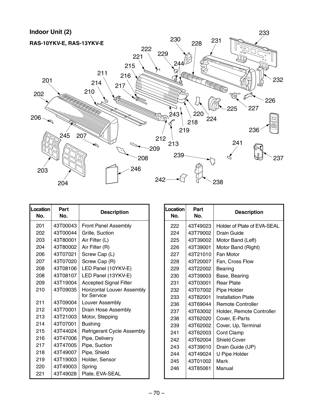
Indoor Unit (2) |
|
|
| 230 |
|
| 233 |
|
|
| 228 | 231 |
| ||
222 |
|
|
| ||||
|
|
|
|
|
| ||
|
| 221 | 229 |
|
|
|
|
|
|
| 244 |
|
|
| |
|
| 215 |
|
|
|
| |
|
|
|
|
|
|
| |
| 211 | 216 |
|
|
|
| 232 |
201 |
|
|
|
|
| ||
214 | 217 |
|
|
|
| ||
|
|
|
|
|
| ||
| 210 |
|
|
|
|
| |
202 |
|
|
|
|
|
| |
|
|
|
|
|
| 226 | |
|
|
|
|
|
|
| |
|
|
|
| 243 | 220 | 225 | 227 |
206 |
|
|
| 224 |
| ||
|
|
| 218 |
| |||
|
|
|
|
|
| ||
245 | 207 |
|
| 219 |
|
| 236 |
| 212 |
|
| 241 |
| ||
|
|
| 213 |
|
| ||
|
|
| 209 |
|
| ||
|
|
| 239 |
|
|
| |
|
| 208 |
|
|
| 237 | |
|
|
|
|
|
| ||
203 |
| 246 |
|
|
|
|
|
204 |
|
| 242 |
|
| 238 |
|
|
|
|
|
|
| ||
Location | Part | Description | |
No. | No. | ||
| |||
|
|
| |
201 | 43T00043 | Front Panel Assembly | |
202 | 43T00044 | Grille, Suction | |
203 | 43T80001 | Air Filter (L) | |
204 | 43T80002 | Air Filter (R) | |
206 | 43T07021 | Screw Cap (L) | |
207 | 43T07020 | Screw Cap (R) | |
208 | 43T08106 | LED Panel | |
208 | 43T08107 | LED Panel | |
209 | 43T19004 | Accepted Signal Filter | |
210 | 43T09035 | Horizontal Louver Assembly | |
|
| for Service | |
211 | 43T09004 | Louver Assembly | |
212 | 43T70001 | Drain Hose Assembly | |
213 | 43T21003 | Motor, Stepping | |
214 | 43T07001 | Bushing | |
215 | 43T44024 | Refrigerant Cycle Assembly | |
216 | 43T47006 | Pipe, Delivery | |
217 | 43T47005 | Pipe, Suction | |
218 | 43T49007 | Pipe, Shield | |
219 | 43T19003 | Holder, Sensor | |
220 | 43T49003 | Spring | |
221 | 43T49028 | Plate, | |
|
|
|
Location | Part | Description | |
No. | No. | ||
| |||
|
| ||
222 | 43T49023 Holder of Plate of | ||
22443T79002 Drain Guide
22543T39002 Motor Band (Left)
22643T39001 Motor Band (Right)
22743T21010 Fan Motor
22843T20007 Fan, Cross Flow
22943T22002 Bearing
23043T39003 Base, Bearing
23143T03001 Rear Plate
23243T07002 Pipe Holder
23343T82001 Installation Plate
23643T69044 Remote Controller
23743T63002 Holder, Remote Controller
23843T62020 Cover,
23943T62002 Cover, Up, Terminal
24143T62003 Cord Clamp
24243T62004 Shield Cover
24343T39010 Drain Guide (UP)
24443T49024 U Pipe Holder
24543T01002 Mark
24643T85061 Manual
– 70 –