10-8-5. Checking Method for Each Part
No. | Part name |
| Checking procedure |
|
|
|
|
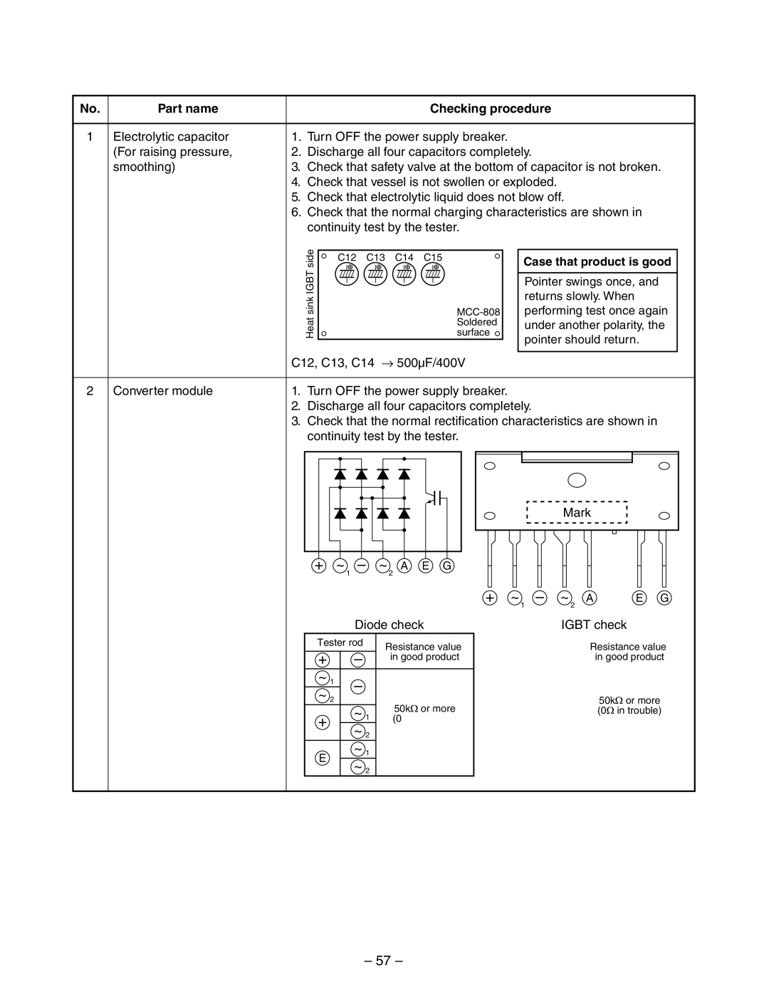
1 | Electrolytic capacitor | 1. | Turn OFF the power supply breaker. |
| (For raising pressure, | 2. | Discharge all four capacitors completely. |
| smoothing) | 3. | Check that safety valve at the bottom of capacitor is not broken. |
4.Check that vessel is not swollen or exploded.
5.Check that electrolytic liquid does not blow off.
6.Check that the normal charging characteristics are shown in continuity test by the tester.
| side | C12 C13 | C14 C15 | Case that product is good |
| IGBT |
|
| Pointer swings once, and |
|
|
|
| |
| sink |
|
| returns slowly. When |
|
|
| performing test once again | |
| Heat |
| surface | under another polarity, the |
|
|
| Soldered | |
|
|
|
| pointer should return. |
| C12, C13, C14 → | 500µF/400V |
| |
2 Converter module | 1. Turn OFF the power supply breaker. |
| ||
2.Discharge all four capacitors completely.
3.Check that the normal rectification characteristics are shown in continuity test by the tester.
|
|
|
|
|
|
|
|
| Mark |
|
| |
+ | ~ | – | ~ | A | E | G |
|
|
|
|
|
|
|
| 1 |
| 2 |
|
|
|
|
|
|
|
|
|
|
|
|
|
| + | ~ | – | ~ | A | E | G |
|
|
|
|
|
|
|
| 1 |
| 2 |
|
|
|
| Diode check |
|
| IGBT check | |||||
Tester rod |
| Resistance value | Tester rod | Resistance value | ||||||
+ |
| – |
| + |
| – | ||||
|
| in good product |
| in good product | ||||||
~ 1 | – |
|
|
| ~ 2 | E |
|
| ||
~ |
|
|
|
| G |
|
|
| ||
2 | ~ |
| 50k | or more |
|
| 50k | or more | ||
+ |
| 1 | ~ | 1 |
| (0 | in trouble) | |||
| (0 | in trouble) | A |
|
| |||||
| ~ 2 | ~ |
|
|
| |||||
|
|
|
| 2 |
|
|
| |||
E |
| ~ | 1 |
|
|
|
|
|
|
|
| ~ 2 |
|
|
|
|
|
|
| ||
|
|
|
|
|
|
|
|
| ||
– 57 –