(3)Contents of operation command signal (Serial signal) from indoor unit controller to outdoor unit controller
The following three types of signals are sent from the indoor unit controller.
•Operation mode set on the remote control
•Compressor revolution command signal defined by indoor temperature and set temperature (Correction along with variation of room temperature and correction of indoor heat exchanger temperature are added.)
•For these two types of signals ( [Operation mode] and [Compressor revolution] ), the outdoor unit controller monitors the input current to the inverter, and performs the followed operation within the range that current does not exceed the allowable value.
•Temperature of indoor heat exchanger by indoor heat exchanger sensor
(Minimum revolution control)
(4)Contents of operation command signal (Serial signal) from outdoor unit controller to indoor unit controller
The following signals are sent from the outdoor unit controller.
•The current operation mode
•The current compressor revolution
•Outdoor temperature
•Existence of protective circuit operation
For transferring of these signals, the indoor unit controller monitors the contents of signals, and judges existence of trouble occurrence.
Contents of judgment are described below.
•Whether distinction of the current operation status meets to the operation command signal
•Whether protective circuit operates
When no signal is received from the outdoor unit controller, it is assumed as a trouble.
8-1-1. Capacity Control
The cooling and heating capacity is varied by changing compressor motor speed. The inverter changes compressor motor speed by changing AC
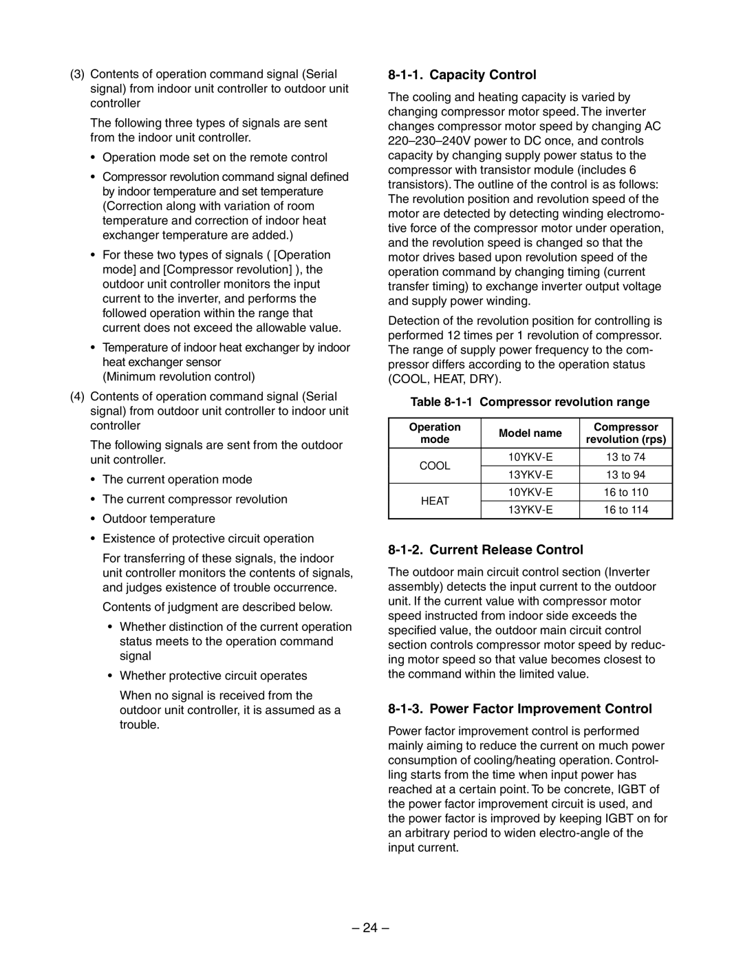
Detection of the revolution position for controlling is performed 12 times per 1 revolution of compressor. The range of supply power frequency to the com- pressor differs according to the operation status (COOL, HEAT, DRY).
Table 8-1-1 Compressor revolution range
Operation | Model name | Compressor | |
mode | revolution (rps) | ||
| |||
|
|
| |
COOL | 13 to 74 | ||
|
| ||
13 to 94 | |||
| |||
|
|
| |
HEAT | 16 to 110 | ||
|
| ||
16 to 114 | |||
| |||
|
|
|
8-1-2. Current Release Control
The outdoor main circuit control section (Inverter assembly) detects the input current to the outdoor unit. If the current value with compressor motor speed instructed from indoor side exceeds the specified value, the outdoor main circuit control section controls compressor motor speed by reduc- ing motor speed so that value becomes closest to the command within the limited value.
8-1-3. Power Factor Improvement Control
Power factor improvement control is performed mainly aiming to reduce the current on much power consumption of cooling/heating operation. Control- ling starts from the time when input power has reached at a certain point. To be concrete, IGBT of the power factor improvement circuit is used, and the power factor is improved by keeping IGBT on for an arbitrary period to widen
– 24 –