4. WIRING DIAGRAM
FAN MOTOR
|
|
|
|
|
|
|
| LOUVER |
|
|
|
|
|
|
|
|
|
| |||||
|
|
|
|
|
|
|
|
|
|
|
|
|
|
|
| ||||||||
|
|
|
|
| MOTOR |
|
|
|
|
|
| DC MOTOR | |||||||||||
|
|
|
|
|
|
|
|
|
|
|
|
| BLU | PNK | YEL | ORN | RED | BRW |
|
|
|
|
|
|
|
|
|
|
|
|
|
|
|
|
|
| 6 | 5 | 4 | 3 | 2 | 1 | 5 | 4 | 3 | 2 | 1 |
|
|
|
|
|
|
|
|
|
|
|
|
| 6 | 5 | 4 | 3 | 2 | 1 | 5 | 4 | 3 | 2 | 1 |
|
|
|
| R109 |
|
|
|
|
|
|
|
| CN07 |
| 5 |
| CN10 |
| 6 | ||||
|
|
| BLK | VARISTOR |
|
| R116 |
|
|
|
|
|
|
|
|
|
|
|
| ||||
|
|
|
|
|
|
|
|
|
|
|
|
|
|
|
|
|
|
|
| ||||
|
|
|
|
|
|
|
|
|
| IC04 |
|
|
|
|
|
|
|
|
|
| |||
|
|
| P04 |
|
| J04 |
|
|
|
|
|
|
|
|
|
|
|
| |||||
|
|
| SG01 DSA |
|
|
|
|
|
|
|
|
|
|
|
|
|
|
|
| ||||
|
|
|
|
|
|
|
|
|
|
|
|
|
|
|
|
|
|
|
| ||||
|
|
|
|
|
|
|
|
|
|
|
| L01 |
|
|
|
|
|
|
|
|
|
| |
|
|
|
| T6,3A 250V |
|
|
|
|
|
|
|
| R01 |
|
|
|
|
|
|
| |||
|
|
|
|
|
|
|
|
|
|
|
|
|
|
|
|
|
|
|
| ||||
|
|
|
| F01 FUSE |
|
|
|
|
|
|
|
|
|
|
|
|
| DB01 |
| TO1 |
| ||
|
|
|
|
| R21 |
|
|
|
|
|
|
|
|
|
|
|
|
|
|
| DC35V | ||
|
|
|
| 3 |
|
|
|
|
|
|
|
|
|
|
|
|
|
|
|
| |||
|
|
|
|
|
|
|
|
|
|
|
|
|
|
|
|
|
|
|
|
| |||
| INDOOR |
|
|
|
|
|
|
|
|
|
|
|
|
|
|
|
|
|
|
|
| ||
|
|
|
|
|
|
|
|
|
|
|
|
|
|
|
|
|
|
|
|
| DC12V | ||
| TERMINAL |
|
|
|
|
|
|
|
| C15 | C01 |
|
| C02 |
|
|
|
| |||||
| BLOCK |
|
|
|
|
|
|
|
|
|
|
|
|
|
|
|
| ||||||
|
|
|
|
|
|
|
|
|
|
|
|
|
|
|
|
|
|
|
|
|
| ||
| 2 |
|
|
|
|
|
|
|
|
|
|
|
|
|
|
|
|
|
|
|
|
| DC7V |
| 1 BLK | CN30 |
|
|
|
|
|
|
|
|
|
|
|
|
|
|
|
|
|
|
| DC0V | |
| 2 | WHI |
|
|
|
|
|
|
|
| MAIN P.C. BOARD |
|
|
|
| ||||||||
|
|
|
|
|
|
|
|
| C06 |
|
| ||||||||||||
| 3 | RED |
|
|
|
|
|
|
|
|
|
|
|
|
|
| IC02 | ||||||
|
|
|
|
|
|
|
|
|
|
|
|
|
|
|
|
|
|
|
|
|
|
| |
|
| GRN & YEL |
|
|
|
|
|
|
|
|
|
|
|
|
|
|
|
|
|
|
|
| |
|
|
|
| CN23 |
|
|
|
|
|
|
|
|
|
|
|
|
|
| IC |
|
|
|
|
|
|
|
|
|
| CN13 |
| 4 |
|
|
| CN03 | IC01 |
|
|
| |||||||
OUTDOOR INDOOR |
|
|
|
|
|
|
|
|
| CN01 |
| ||||||||||||
|
| 1 | 2 | 3 | 4 | 5 | 6 | 7 | 8 | 9 |
|
| 1 | 2 |
|
| 1 | 2 |
|
| |||
UNIT | UNIT |
|
|
|
|
|
|
|
| ||||||||||||||
|
| BLU | BLU | BLU | BLU | BLU | BLU | PNK | BLK | WHI |
|
| 1 | 2 |
|
| 1 | 2 |
|
| |||
|
|
|
|
|
|
|
|
|
|
| |||||||||||||
|
|
|
|
|
|
| BLK | BLK |
|
| BLK | BLK |
|
| |||||||||
|
|
|
| 1 | 1 | 2 | 3 | 4 | 5 | 6 | 7 | 8 | 9 |
|
|
|
|
|
|
|
|
| HEAT |
|
|
|
| 1 2 3 4 5 6 7 8 9 CN25 |
|
|
|
|
|
|
|
| |||||||||||
|
|
|
|
|
|
|
| THERMO |
|
| EXCHANGER | ||||||||||||
|
|
|
|
| INFRARED RAYS RECEIVE |
|
|
|
| SENSOR |
|
|
| SENSOR | |||||||||
|
|
|
|
| AND INDICATION PARTS |
|
|
|
| (TA) |
|
|
| (TC) | |||||||||
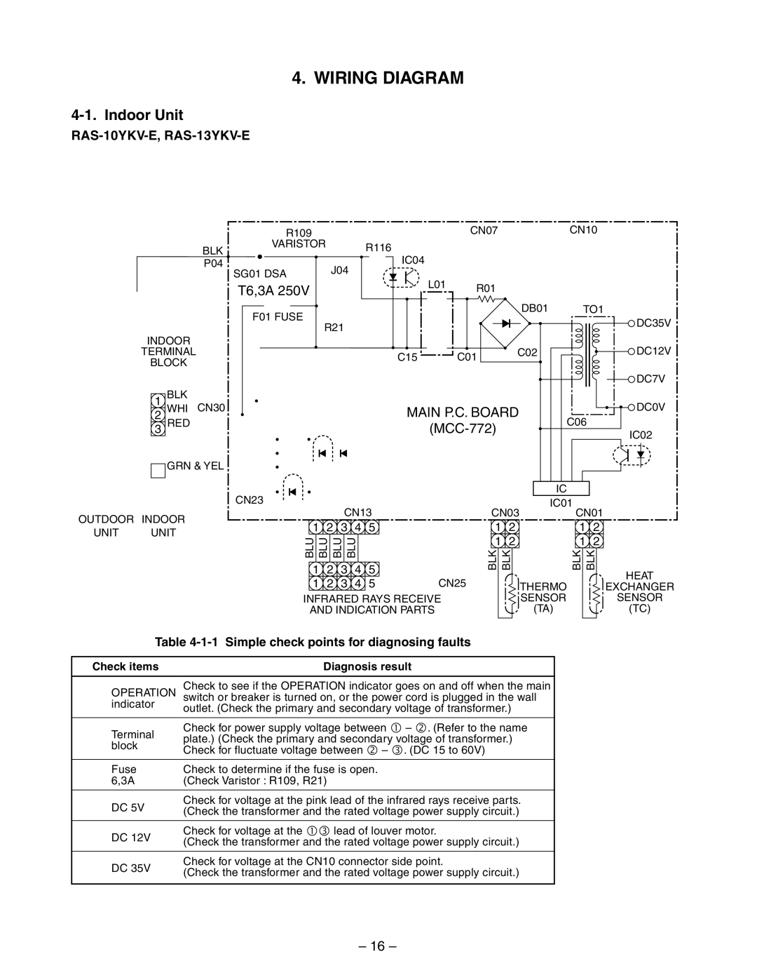
Table 4-1-1 Simple check points for diagnosing faults
Check items |
| Diagnosis result |
|
|
|
OPERATION |
| Check to see if the OPERATION indicator goes on and off when the main |
| switch or breaker is turned on, or the power cord is plugged in the wall | |
indicator |
| outlet. (Check the primary and secondary voltage of transformer.) |
|
| |
|
|
|
Terminal |
| Check for power supply voltage between Q – R. (Refer to the name |
| plate.) (Check the primary and secondary voltage of transformer.) | |
block |
| |
| Check for fluctuate voltage between R – S. (DC 15 to 60V) | |
|
| |
|
|
|
Fuse |
| Check to determine if the fuse is open. |
6,3A |
| (Check Varistor : R109, R21) |
|
|
|
DC 5V |
| Check for voltage at the pink lead of the infrared rays receive parts. |
| (Check the transformer and the rated voltage power supply circuit.) | |
|
| |
|
|
|
DC 12V |
| Check for voltage at the QS lead of louver motor. |
| (Check the transformer and the rated voltage power supply circuit.) | |
|
| |
|
|
|
DC 35V |
| Check for voltage at the CN10 connector side point. |
| (Check the transformer and the rated voltage power supply circuit.) | |
|
| |
|
| |
For detailed diagnostic procedure, refer to the service data. | ||
DSA : Surge Absorber |
| |
COLOR
IDENTIFICATION
BRW : BROWN
RED : RED
WHI : WHITE
YEL : YELLOW
BLU : BLUE
BLK : BLACK
GRY : GRAY
PNK : PINK
ORN : ORANGE
GRN : GREEN &
&YEL YELLOW
– 16 –