8-2-3. Heating Operation
Transferring of heating operation signal from indoor unit to outdoor unit starts.
The indoor fan motor operates by the room tempera- ture when selecting “AUTO” of “FAN” as shown in Fig.
However, to prevent cold draft, revolution speed of the fan is restricted by indoor heat exchanger when air flow is AUTO (Fig.
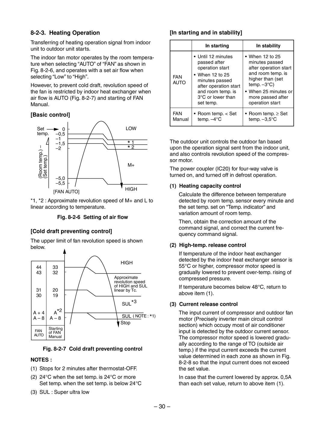
[Basic control]
Set | 0 |
| LOW |
| |||
temp. |
|
| |
| * 1 | ||
– | |||
(Roomtemp.) temp.)(Set |
| * 2 | |
| |||
|
| M+ | |
[In starting and in stability]
| In starting | In stability | |
|
|
| |
| • Until 12 minutes | • When 12 to 25 | |
| passed after | minutes passed | |
| operation start | after operation start | |
FAN | • When 12 to 25 | and room temp. is | |
higher than (set | |||
minutes passed | |||
AUTO | |||
temp. | |||
after operation start | |||
| |||
|
| ||
| and room temp. is | • When 25 minutes or | |
| 3°C or lower than | more passed after | |
| set temp. | operation start | |
|
|
| |
FAN | • Room temp. < Set | • Room temp. ≥ Set | |
Manual | temp. | temp. | |
|
|
|
The outdoor unit controls the outdoor fan based upon the operation signal sent from the indoor unit, and also controls revolution speed of the compres- sor motor.
[FAN AUTO]
HIGH
The power coupler (IC20) for
(1) Heating capacity control |
Calculate the difference between temperature |
*1, *2 : Approximate revolution speed of M+ and L to linear according to temperature.
Fig. 8-2-6 Setting of air flow
[Cold draft preventing control]
The upper limit of fan revolution speed is shown below.
detected by room temp. sensor every minute and |
the set temp. set on “Temp. indicator” and |
variation amount of room temp. |
Then, obtain the correction amount of the |
command signal, and correct the current fre- |
quency command signal. |
(2) |
If temperature of the indoor heat exchanger |
detected by the indoor heat exchanger sensor is |
44 | 33 | |
43 | 32 | |
31 | 20 | |
30 | 19 | |
A + 4 | A*2 | |
A – 8 | A – 8 | |
|
| |
FAN | Starting | |
of FAN | ||
AUTO | ||
Manual | ||
|
HIGH
Approximate revolution speed of HIGH and SUL linear by Tc.
SUL*3
SUL ( NOTE : *1)
![]() Stop
Stop
55°C or higher, compressor motor speed is |
gradually lowered to prevent |
compressed pressure. |
If temperature becomes below 48°C, return to |
above item (1). |
(3) Current release control |
The input current of compressor and outdoor fan |
motor (Precisely inverter main circuit control |
section) which occupy most of air conditioner |
input is detected by the outdoor current sensor. |
The compressor motor speed is lowered gradu- |
ally according to the range of TO (outside air |
Fig. 8-2-7 Cold draft preventing control
NOTES :
(1)Stops for 2 minutes after
(2)24°C when the set temp. is 24°C or more Set temp. when the set temp. is below 24°C
(3)SUL : Super ultra low
temp.) if the input current exceeds the current |
value determined in each zone as shown in Fig. |
the set value. |
In case that the current lowered by approx. 0,5A |
than each set value, return to above item (1). |
– 30 –