9-2-3. Electrical Work
How to connect the connecting cable
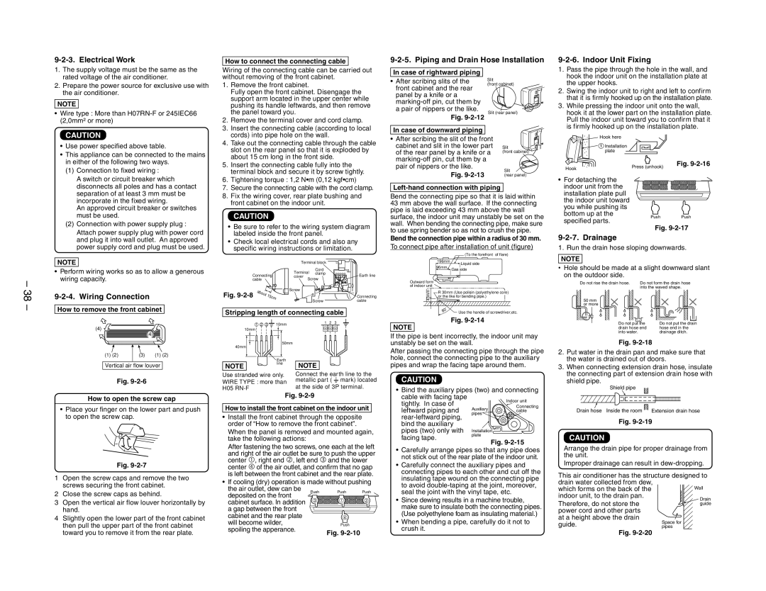
9-2-5. Piping and Drain Hose Installation
9-2-6. Indoor Unit Fixing
1.The supply voltage must be the same as the rated voltage of the air conditioner.
2.Prepare the power source for exclusive use with the air conditioner.
NOTE
•Wire type : More than
Wiring of the connecting cable can be carried out without removing of the front cabinet.
1. | Remove the front cabinet. |
| Fully open the front cabinet. Disengage the |
| support arm located in the upper center while |
| pushing its handle leftwards, and then remove |
| the panel toward you. |
2. | Remove the terminal cover and cord clamp. |
In case of rightward piping
•After scribing slits of the front cabinet and the rear panel by a knife or a
Fig.
Slit
(front cabinet)
Slit (rear panel)
1. | Pass the pipe through the hole in the wall, and |
| hook the indoor unit on the installation plate at |
| the upper hooks. |
2. | Swing the indoor unit to right and left to confirm |
| that it is firmly hooked up on the installation plate. |
3. | While pressing the indoor unit onto the wall, |
| hook it at the lower part on the installation plate. |
| Pull the indoor unit toward you to confirm that it |
| is firmly hooked up on the installation plate. |
CAUTION
• | Use power specified above table. |
• | This appliance can be connected to the mains |
3. | Insert the connecting cable (according to local |
| cords) into pipe hole on the wall. |
4. | Take out the connecting cable through the cable |
| slot on the rear panel so that it is exploded by |
| about 15 cm long in the front side. |
In case of downward piping |
|
|
• After scribing the slit of the front |
| |
cabinet and slit in the lower part | Slit | |
of the rear panel by a knife or a | (front cabinet) | |
| ||
1 | Hook here |
| 1 Installation |
| plate |
in either of the following two ways. |
(1) Connection to fixed wiring : |
A switch or circuit breaker which |
disconnects all poles and has a contact |
separation of at least 3 mm must be |
incorporate in the fixed wiring. |
An approved circuit breaker or switches |
must be used. |
(2) Connection with power supply plug : |
Attach power supply plug with power cord |
5. | Insert the connecting cable fully into the |
| terminal block and secure it by screw tightly. |
6. | Tightening torque : 1,2 N•m (0,12 kgf•cm) |
7. | Secure the connecting cable with the cord clamp. |
8. | Fix the wiring cover, rear plate bushing and |
| front cabinet on the indoor unit. |
CAUTION
• Be sure to refer to the wiring system diagram |
labeled inside the front panel. |
pair of nippers or the like. | Slit | |
Fig. | ||
(rear panel) |
Left-hand connection with piping
Bend the connecting pipe so that it is laid within
43 mm above the wall surface. If the connecting pipe is laid exceeding 43 mm above the wall surface, the indoor unit may unstably be set on the wall. When bending the connecting pipe, make sure to use spring bender so as not to crush the pipe.
2
Hook
•For detaching the indoor unit from the installation plate pull the indoor unit toward you while pushing its bottom up at the specified parts.
Press (unhook) | Fig. |
|
Push Push
Fig.
– 38 –
and plug it into wall outlet. An approved |
power supply cord and plug must be used. |
NOTE
•Perform wiring works so as to allow a generous wiring capacity.
9-2-4. Wiring Connection
How to remove the front cabinet
• Check local electrical cords and also any |
specific wiring instructions or limitation. |
|
|
|
| Terminal block |
|
|
|
|
| Cord |
|
Connecting |
| Terminal clamp | Earth line | ||
| cover | ||||
cable |
|
| Screw |
| |
Fig. | abo |
|
| Screw |
|
|
|
|
| ||
ut | 15c | m |
| Connecting | |
|
|
| Screw | cable | |
|
|
|
| ||
Stripping length of connecting cable
Bend the connection pipe within a radius of 30 mm.
To connect pipe after installation of unit (figure)
(To the forefront of flare)
196mm
![]() Liquid side
Liquid side
96mm![]() Gas side
Gas side
Outward form of indoor unit
43mm | R 30mm (Use polisin (polyethylene core) |
| or the like for bending pipe.) |
|
|
80˚ | Use the handle of screwdriver,etc. |
|
9-2-7. Drainage
1. Run the drain hose sloping downwards.
NOTE
•Hole should be made at a slight downward slant on the outdoor side.
Do not rise the drain hose. | Do not form the drain hose |
| into the waved shape. |
50mm or more
(4) ![]()
(4)
1 2 3 ![]() 10mm
10mm
10mm |
50mm
40mm
1 2 3
Fig.
NOTE
If the pipe is bent incorrectly, the indoor unit may unstably be set on the wall.
|
|
|
|
|
Do not put the | Do not put the drain | |||
drain hose end | hose end in the | |||
into water. | drainage ditch. | |||
Fig.
(1) (2) | (3) | (1) (2) |
Vertical air flow louver
NOTE
![]() Earth line
Earth line
NOTE
After passing the connecting pipe through the pipe hole, connect the connecting pipe to the auxiliary pipes and wrap the facing tape around them.
2. | Put water in the drain pan and make sure that |
| the water is drained out of doors. |
3. | When connecting extension drain hose, insulate |
Fig.
Use stranded wire only. WIRE TYPE : more than H05
Connect the earth line to the metallic part ( ![]() mark) located
mark) located
at the side of 3P terminal.
CAUTION
• Bind the auxiliary pipes (two) and connecting
the connecting part of extension drain hose with |
shield pipe.
Shield pipe
How to open the screw cap
•Place your finger on the lower part and push to open the screw cap.
Fig.
1Open the screw caps and remove the two screws securing the front cabinet.
2Close the screw caps as behind.
3Open the vertical air flow louver horizontally by hand.
4Slightly open the lower part of the front cabinet then pull the upper part of the front cabinet toward you to remove it from the rear plate.
Fig.
How to install the front cabinet on the indoor unit
• Install the front cabinet through the opposite order of “How to remove the front cabinet”.
When the panel is removed and mounted again, take the following actions:
After fastening the two screws, one each at the left and right of the air outlet be sure to push the upper center Q, right end R, left end S and the lower center T of the air outlet, and confirm that no gap is left between the front cabinet and the rear plate.
• If cooling (dry) operation is made without pushing
the air outlet, dew can be | Push | Push | Push | |
deposited on the front | ||||
|
|
| ||
cabinet surface. In addition | 3 | 1 | 2 | |
|
|
| ||
a gap between the front |
|
|
| |
cabinet and the rear plate |
| 4 |
| |
will become wilder, |
| Push |
| |
spoiling the apperance. |
| Fig. |
| |
|
|
|
cable with facing tape tightly. In case of leftward piping and
•Carefully arrange pipes so that any pipe does not stick out of the rear plate of the indoor unit.
•Carefully connect the auxiliary pipes and connecting pipes to each other and cut off the insulating tape wound on the connecting pipe to avoid
•Since dewing results in a machine trouble, make sure to insulate both the connecting pipes. (Use polyethylene foam as insulating material.)
•When bending a pipe, carefully do it not to
crush it.
Drain hose | Inside the room | Extension drain hose |
Fig.
CAUTION
Arrange the drain pipe for proper drainage from the unit.
Improper drainage can result in
This air conditioner has the structure designed to drain water collected from dew,
which forms on the back of theWall indoor unit, to the drain pan.
Therefore, do not store the power cord and other parts at a height above the drain
guide. | Space for |
pipes | |
| Fig. |