Return to Section TOC
Return to Section TOC
Return to Section TOC
Return to Section TOC
Return to Master TOC
Return to Master TOC
Return to Master TOC
Return to Master TOC
| TROUBLESHOOTING & REPAIR |
| |
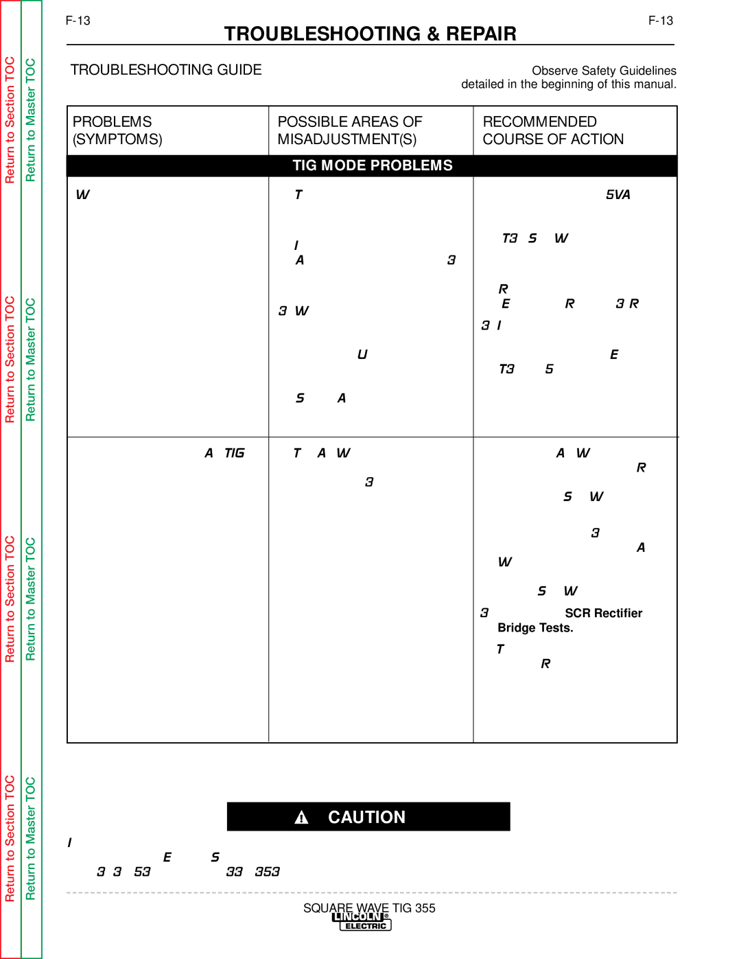
| TROUBLESHOOTING GUIDE | Observe Safety Guidelines | |
|
| detailed in the beginning of this manual. | |
PROBLEMS | POSSIBLE AREAS OF | RECOMMENDED |
| ||
(SYMPTOMS) | MISADJUSTMENT(S) | COURSE OF ACTION |
| ||
|
|
|
|
|
|
|
| TIG MODE PROBLEMS |
|
|
|
Weak high frequency – machine | 1. | The spark gap may be misad- | 1. | Make sure that 115VAC is |
|
has normal welding output. |
| justed. Check and reset per |
| being applied to the primary of |
|
|
| maintenance instructions. |
| the high voltage transformer |
|
| 2. Improper shielding gas flow. |
| (T3). See Wiring Diagram. |
| |
|
|
|
| ||
|
| Adjust for a flow of 10 to 30 | 2. | Check for an open or arcing |
|
|
| CFH (4.7 to 14.1 l/min.) for |
| high frequency component. |
|
|
| most applications. |
| Replace as required. |
|
| 3. Work and electrode cables |
| (Examples: R6, C6, C3, R4) |
| |
|
|
|
| ||
|
| may be in poor condition, | 3. | If spark is weak at the spark |
|
|
| allowing the high frequency to |
| gap, check or replace the high |
|
|
| “leak off.” Use good quality |
| frequency circuit. (Examples: |
|
|
| cables with a high natural rub- |
| T3, L4, L5). |
|
|
| ber content, such as Lincoln |
|
|
|
|
| Stable Arc Cable. Cables |
|
|
|
|
| should be as short as possible. |
|
|
|
|
|
|
|
|
|
Lack of penetration in AC TIG | 1. | The AC Wave Balance control | 1. | Check the AC Wave Balance |
|
welding. |
| may be set improperly – set- |
| control potentiometer (R12) for |
|
|
| tings above 3 give increased |
| correct resistance and proper |
|
|
| penetration. |
| operation. See Wiring |
|
|
|
|
| Diagram. |
|
|
|
| 2. Check leads #443 and #444 |
| |
|
|
|
| for continuity from the AC |
|
|
|
|
| Wave Balance control poten- |
|
|
|
|
| tiometer to the lower control |
|
|
|
|
| panel. See Wiring Diagram. |
|
|
|
| 3. Perform the SCR Rectifier |
| |
|
|
|
| Bridge Tests. |
|
|
|
| 4. The control board may be |
| |
|
|
|
| faulty. Replace. |
|
|
|
|
|
|
|
CAUTION
If for any reason you do not understand the test procedures or are unable to perform the test/repairs safely, con- tact the Lincoln Electric Service Department for electrical troubleshooting assistance before you proceed. Call
SQUARE WAVE TIG 355