Return to Section TOC
Return to Section TOC
Return to Master TOC
Return to Master TOC
TROUBLESHOOTING & REPAIR | |||
|
|
| |
SCR REMOVAL AND AND REPLACEMENT (continued)
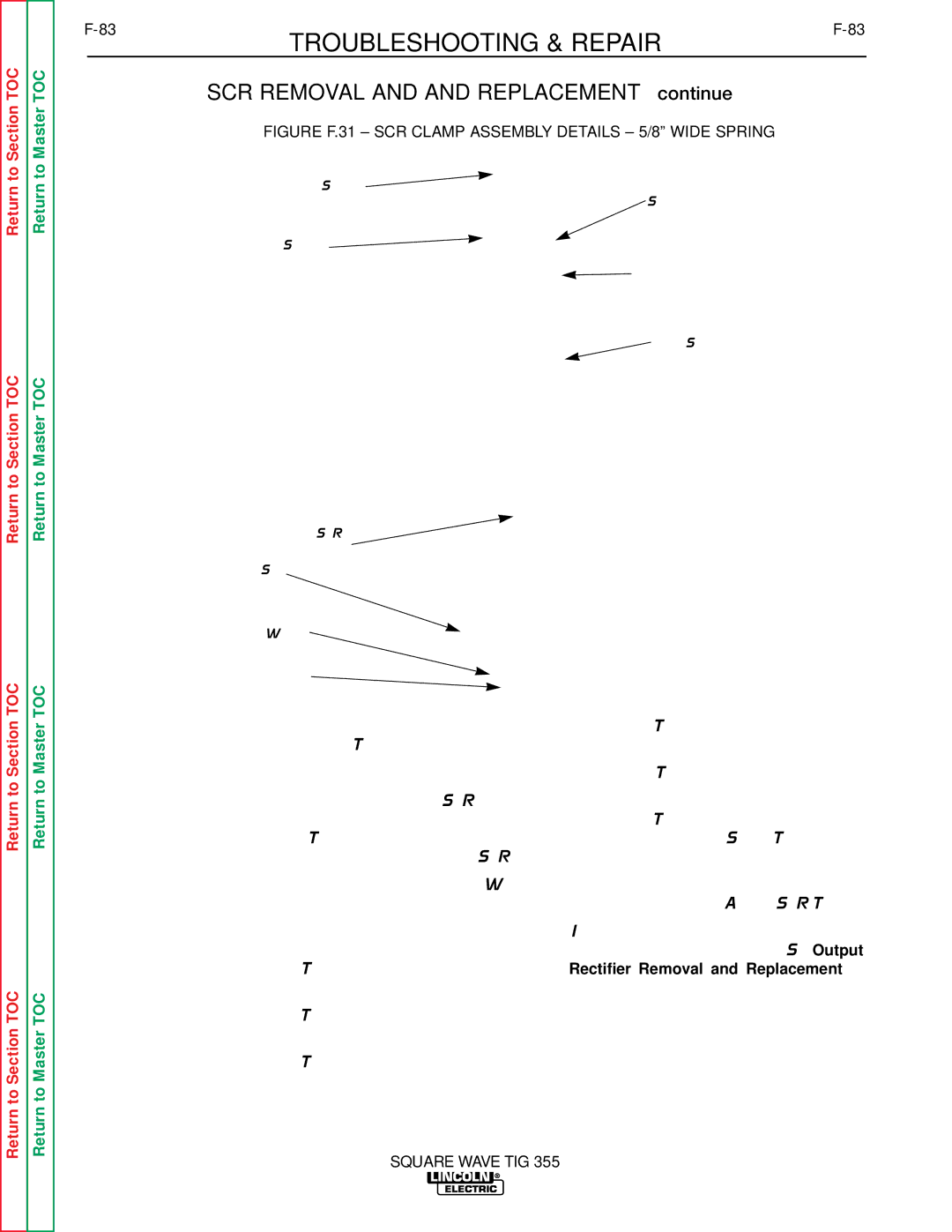
FIGURE F.31 – SCR CLAMP ASSEMBLY DETAILS – 5/8” WIDE SPRING
Cap Screw
Steel Pressure Pad
Leaf Spring
![]() Plastic Housing
Plastic Housing
![]() Heat Sink
Heat Sink
SCR
Heat Sink
Plain Washer
Clamp Nut
Return to Section TOC
Return to Section TOC
Return to Master TOC
Return to Master TOC
Clamping procedure for
a.Do not turn the nuts. While holding the nuts stationary, turn the cap screws only with the following procedure.
b.Tighten first cap screw 1/4 turn.
c.Tighten second cap screw 1/2 turn.
d.Tighten the first cap screw 1/2 turn.
e.Tighten the second cap screw 1/4 turn.
f.Tighten the first cap screw 1/8 turn.
g.Tighten the second cap screw 1/8 turn. Stop. The assembly now has the proper clamping force.
8)Perform the Active SCR Test.
10.Install the output rectifier heat sink assem- bly back into the machine. See Output Rectifier Removal and Replacement in this section of the manual.
SQUARE WAVE TIG 355