Camco P.7 Series, P.9 Series, P.5 Series, P Series, P.0 Series Cooling, Ground Lift, Mode Indicators

Page 15

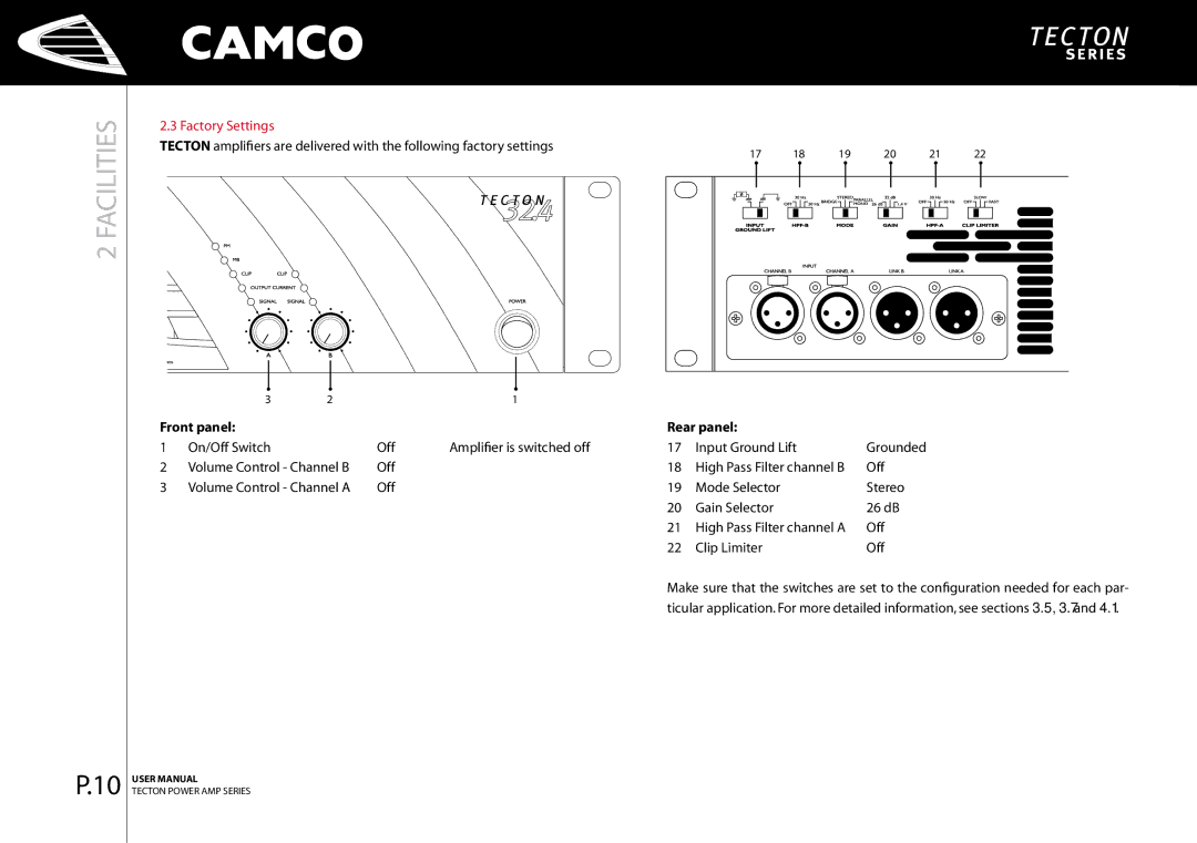
3 INSTALLATION

P.13

3.4 Cooling

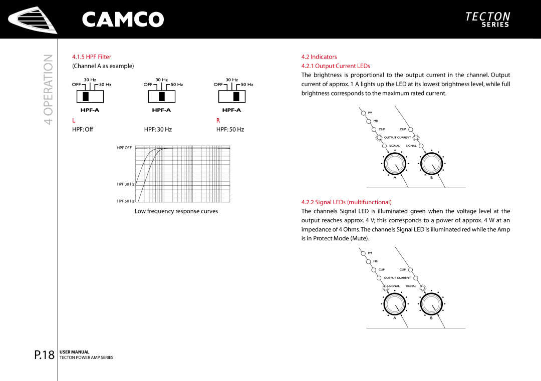
Under normal operation of the power amp, overheating should never be a problem. The air is taken in from the front and out through the back, it is of course essential that while the power amp is running air is able to circulate around it freely.

The efficiency of the cooling will depend on the immediate environment (e.g. an enclosed rack, direct sunlight). If the amp is installed in a case, the open area at the back of the case must be at least 140 cm².This area should be in line with the amp.

If this can not be achieved a forced ventilation system has to be used.

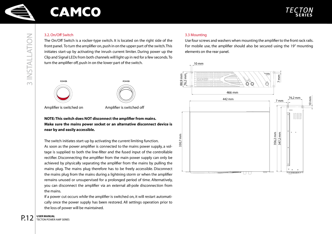
3.5 Ground Lift

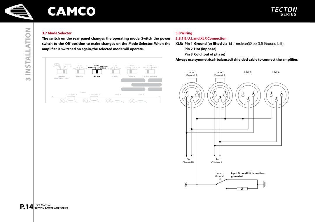
The input signal ground (pin 1 for all 4 XLRs) is connected to the ground of the mains supply. In order to avoid ground loops, this connection can be separated via a resistor. The ground potential of the power amp and the ground of the loudspeaker always remain connected to the ground of the mains supply regardless of the setting of this switch.

Lift Position


Ground Position


to Pin 1

of the XLRs

Removing or taping the mains connector ground is illegal and dangerous.

DO NOT REMOVE MAINS CONNECTOR GROUND

IT IS ILLEGAL AND DANGEROUS

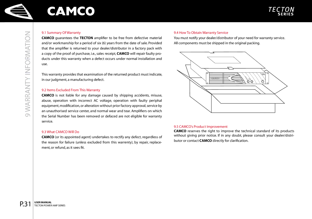
USER MANUAL

TECTON POWER AMP SERIES

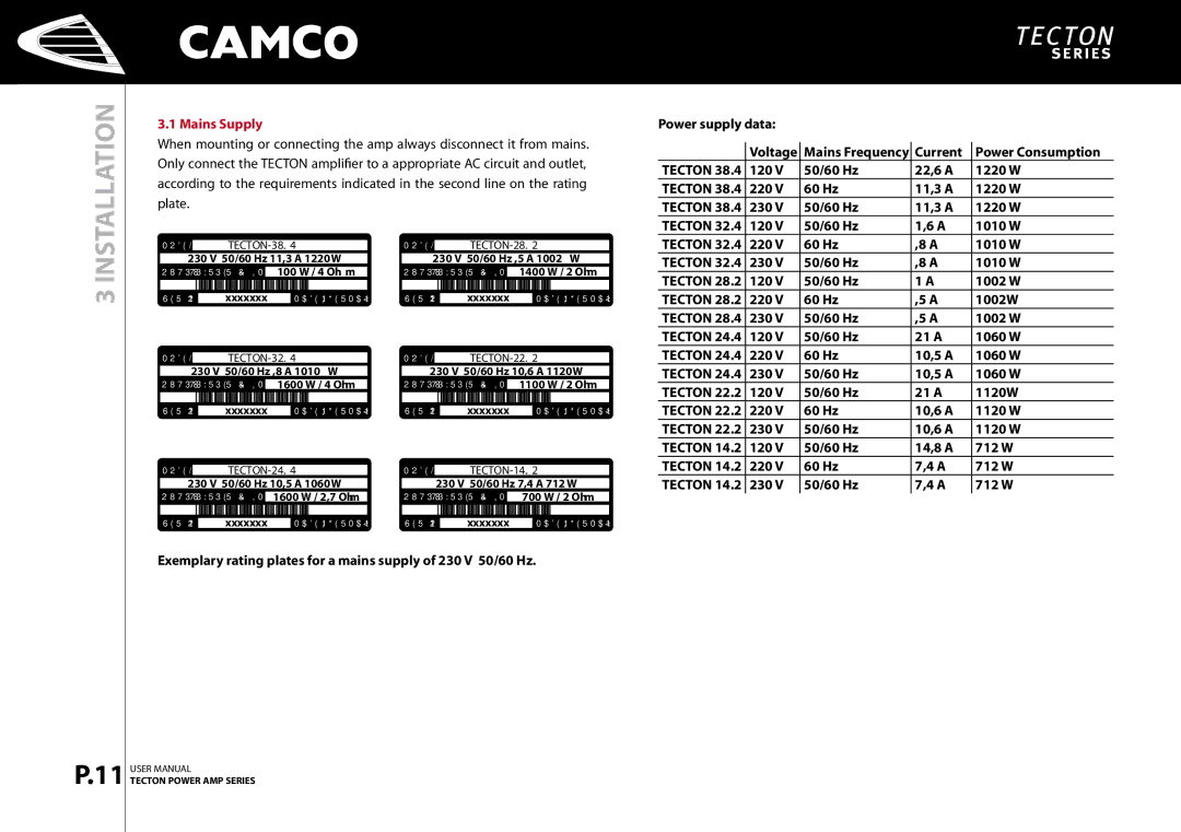
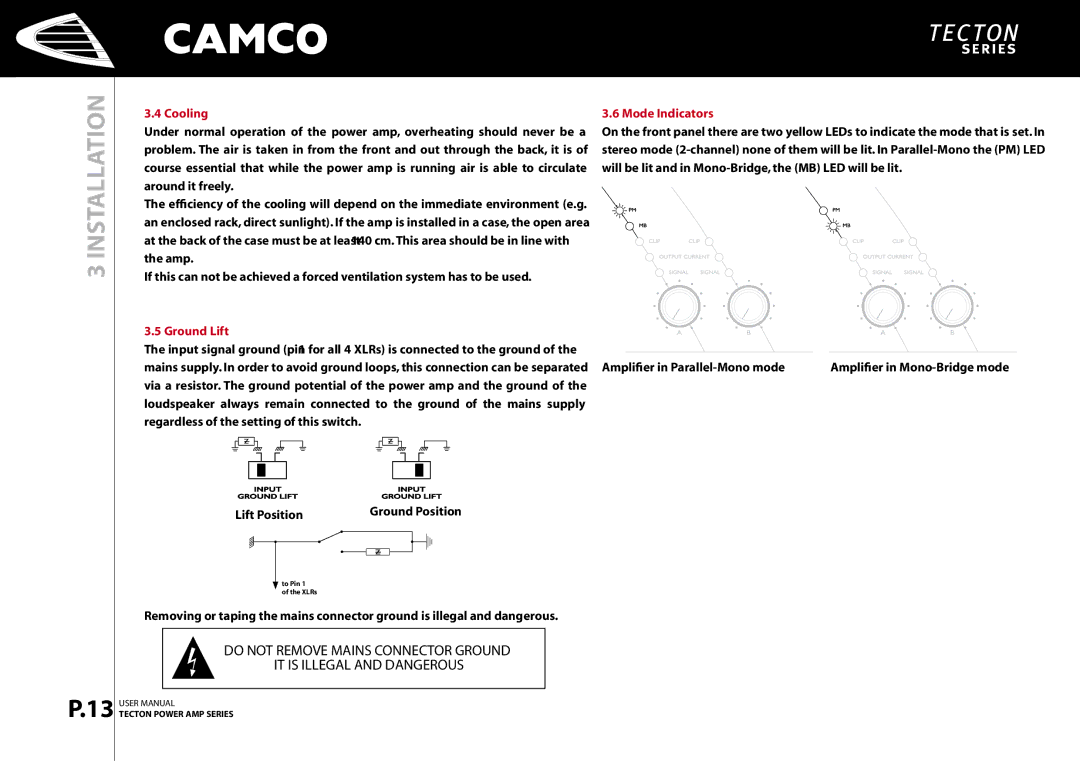
3.6 Mode Indicators

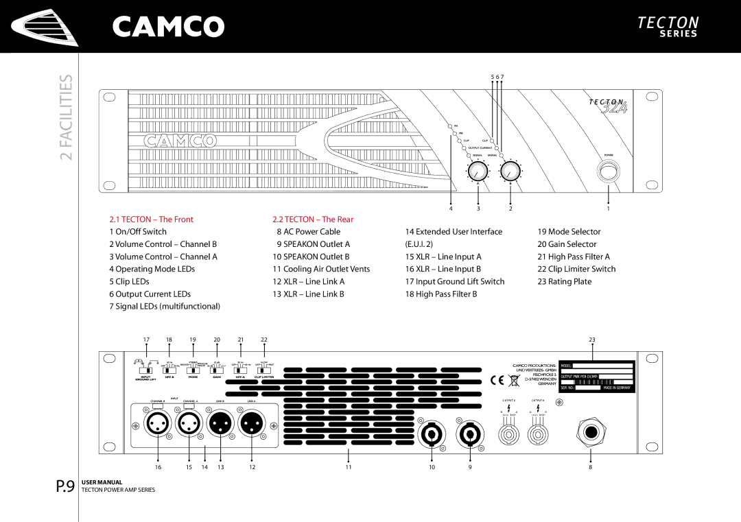
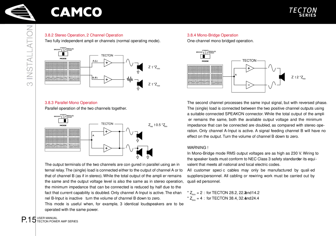
On the front panel there are two yellow LEDs to indicate the mode that is set. In stereo mode (2-channel) none of them will be lit. In Parallel-Mono the (PM) LED will be lit and in Mono-Bridge, the (MB) LED will be lit.

Amplifier in Parallel-Mono mode

Amplifier in Mono-Bridge mode

Image 15
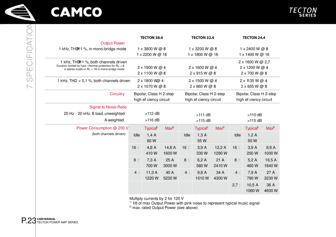
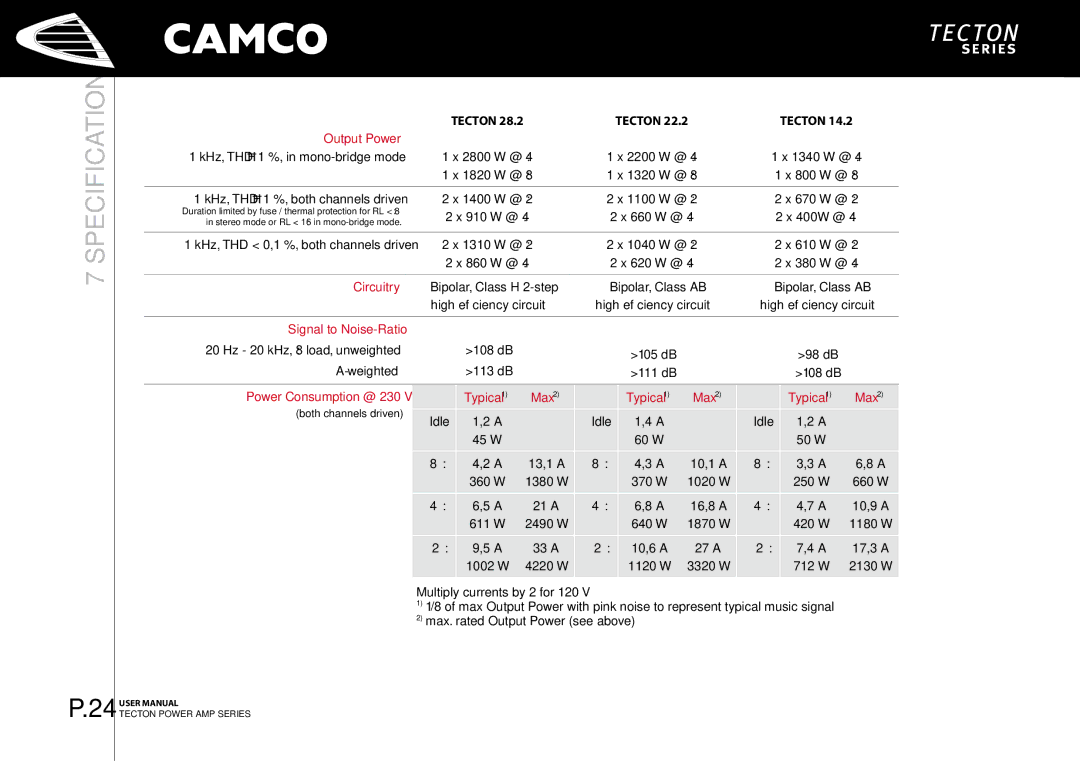
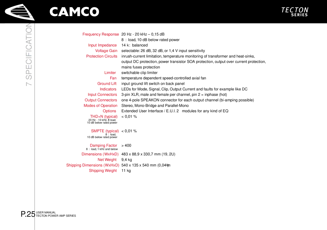
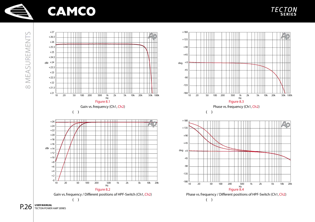
Contents Page Page Information for USE for Important Safety Instructions Important Safety InstructionsExplanation of Symbols / Safety Safety Declares that the product with the model name EC Declaration of ConformityManufacturers Name Manufacturers AddressContents Welcome Welcome to CamcoUnpacking Amplifier Tecton is a Class-H power amplifier with a power outputTecton The Front Tecton The Rear FacilitiesFront panel Factory SettingsMains Supply InstallationMounting On/Off SwitchMode Indicators CoolingGround Lift Wiring 1 E.U.I. and XLR Connection Mode SelectorStereo Operation, 2 Channel Operation Mono-Bridge Operation One-channel mono bridged operationParallel-Mono Operation Speakon Connection OperationGain and Input Sensitivity Controls Volume ControlLimiter Switch Gain SelectorSignal LEDs multifunctional Indicators Output Current LEDsDC Protection Power Amp Protection Systems 4.3.1 Clip LimiterClip LEDs SOA ProtectionFuse Protection Mains Protections Inrush Current LimitationMains Over Voltage Detection Mains Failure DetectionWhat Are The Possibilities Using The E.U.I.2? OptionsE.U.I.2 Extended User Interface Troubleshooting Power Consumption @ 230 SpecificationOutput Power Signal to Noise-Ratio1400 W @ 2 Ω 1100 W @ 2 Ω 670 W @ 2 Ω Dimensions WxHxD IndicatorsInput Connectors Output ConnectorsMeasurements of a typical performance MeasurementsMeasurements of a typical performance of Tecton Ch1, Ch2 Measurements of a typical performance of Tecton Tecton 24.4 Measurements of a typical performance Tecton 14.2 Measurements of a typical performance Warranty Information Shipping Address Expired WarrantyNature Of Problem Owner’s InformationMaintenance Information DECOMISSIONINGINFORMATION/12Decomissioning Facsimile Company InformationMailing Address Telephone