Camco P.8 Series, P.9 Series, P.5 Series, P Series, P.0 Series manual Operation, Speakon Connection

Page 18
Input Channel B
USER MANUAL
TECTON POWER AMP SERIES

4 OPERATION

P.16

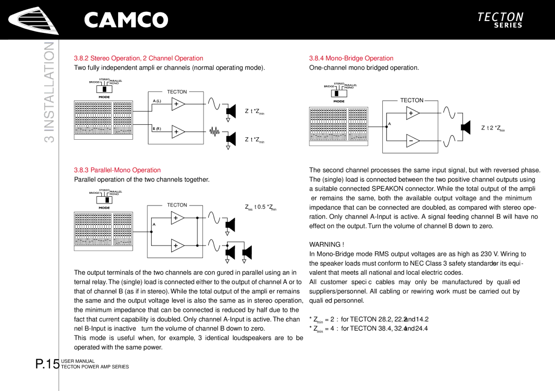
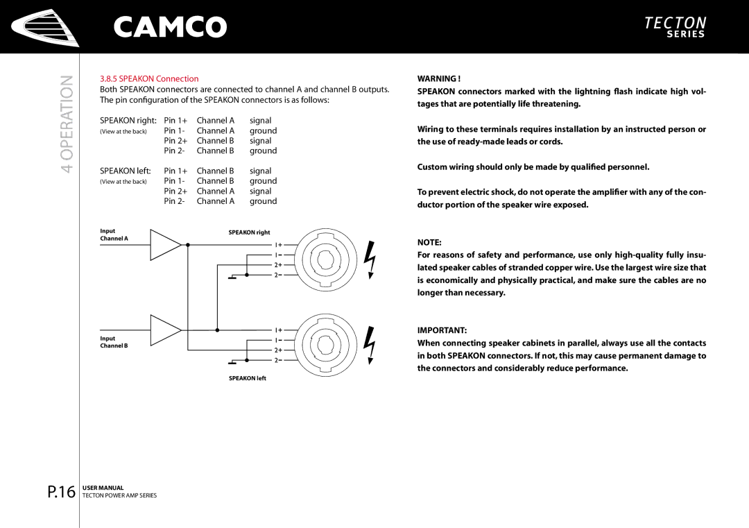
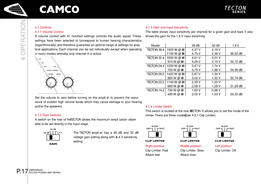
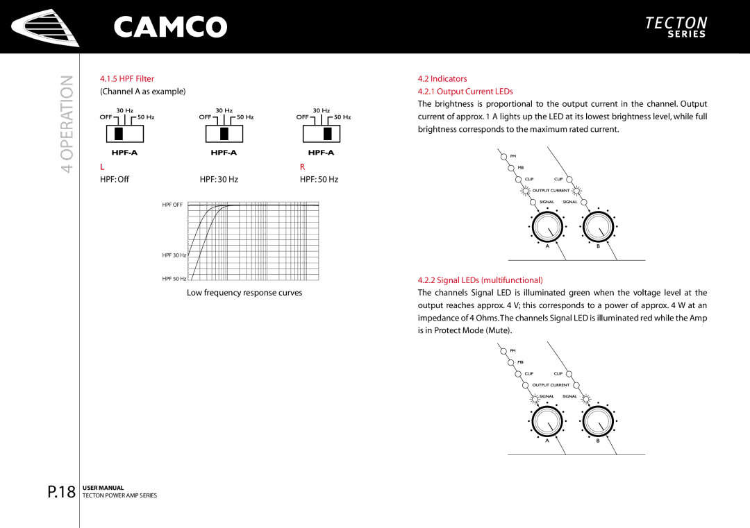
3.8.5 SPEAKON Connection

Both SPEAKON connectors are connected to channel A and channel B outputs. The pin configuration of the SPEAKON connectors is as follows:

SPEAKON right:

Pin 1+

Channel A


signal

(View at the back)

Pin 1-

Channel A


ground


Pin 2+

Channel B


signal


Pin 2-

Channel B


ground

SPEAKON left:

Pin 1+

Channel B


signal

(View at the back)

Pin 1-

Channel B


ground


Pin 2+

Channel A


signal


Pin 2-

Channel A


ground

Input


SPEAKON right

Channel A


SPEAKON left

WARNING !

SPEAKON connectors marked with the lightning flash indicate high vol­ tages that are potentially life threatening.

Wiring to these terminals requires installation by an instructed person or the use of ready-made leads or cords.

Custom wiring should only be made by qualified personnel.

To prevent electric shock, do not operate the amplifier with any of the con­ ductor portion of the speaker wire exposed.

NOTE:

For reasons of safety and performance, use only high-quality fully insu­ lated speaker cables of stranded copper wire. Use the largest wire size that is economically and physically practical, and make sure the cables are no longer than necessary.

IMPORTANT:

When connecting speaker cabinets in parallel, always use all the contacts in both SPEAKON connectors. If not, this may cause permanent damage to the connectors and considerably reduce performance.
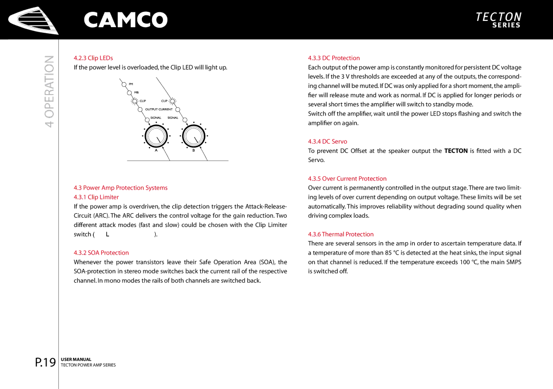
Image 18
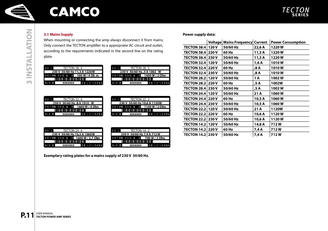
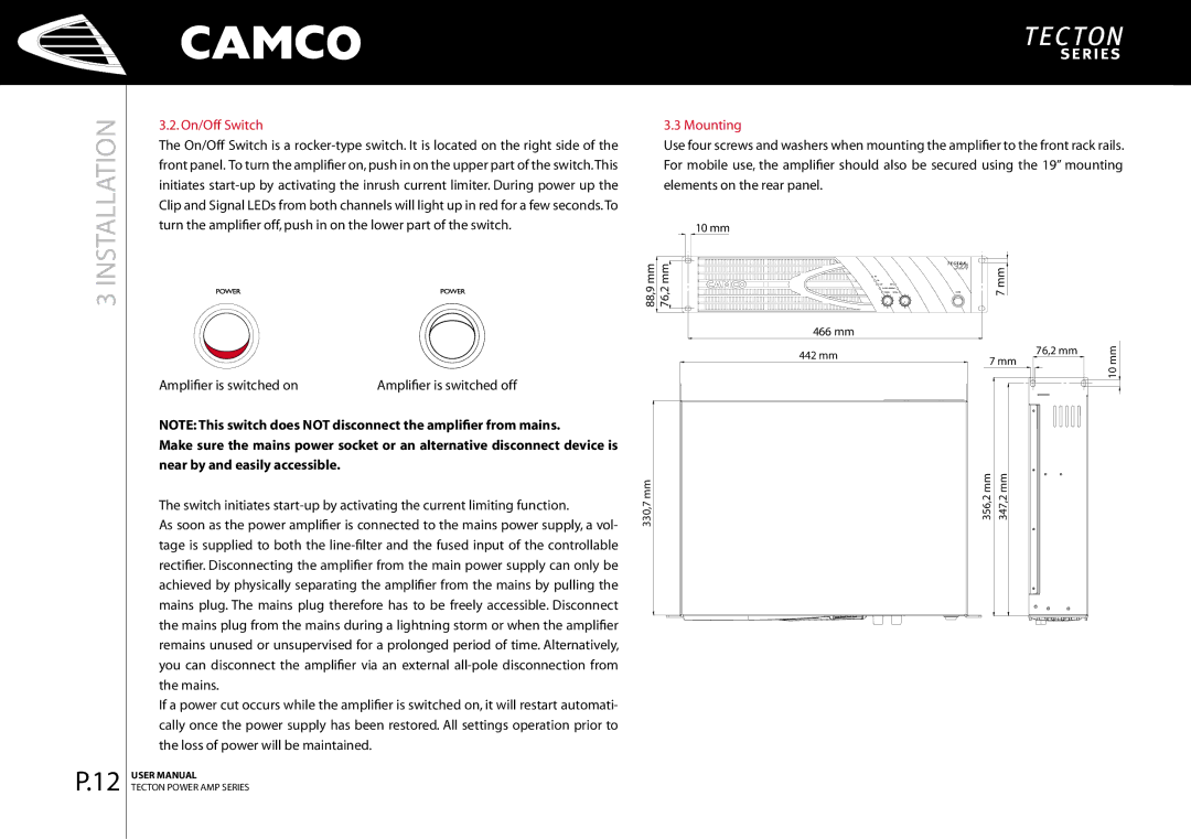
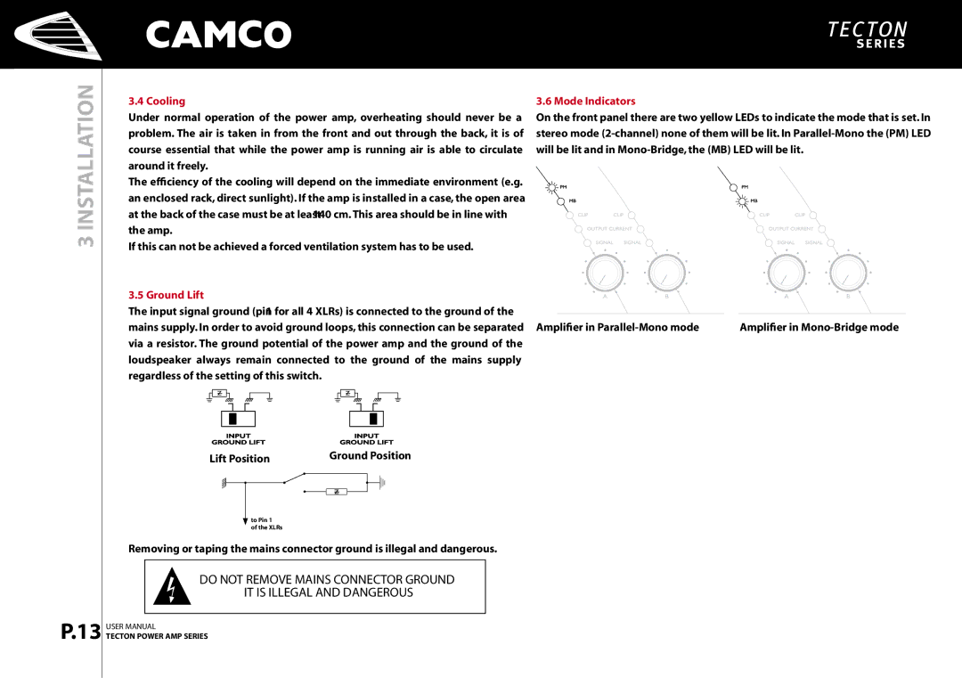
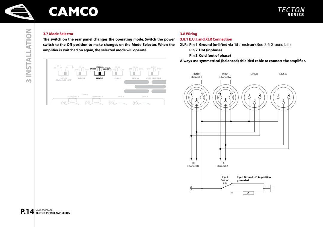
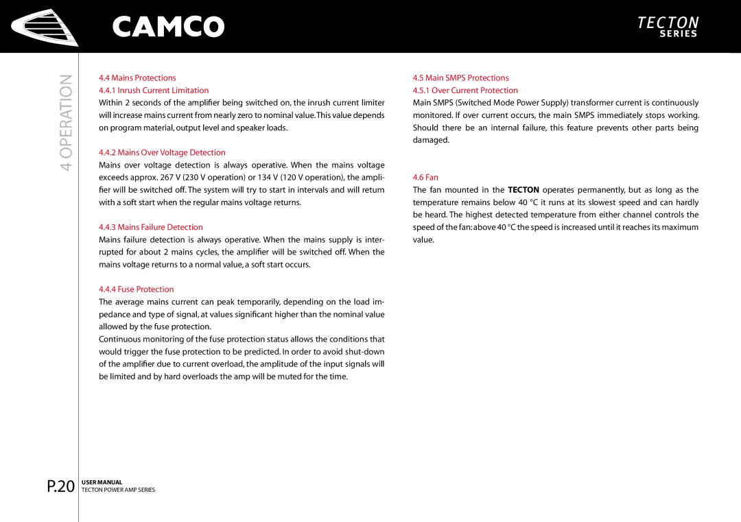
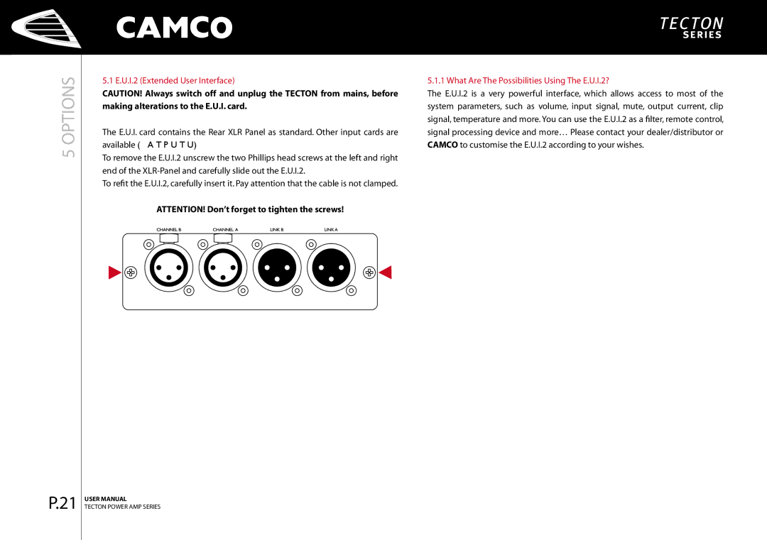
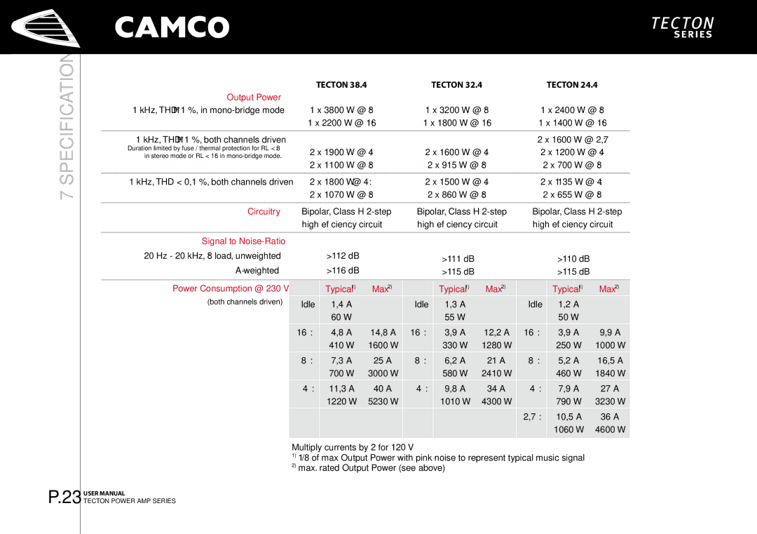
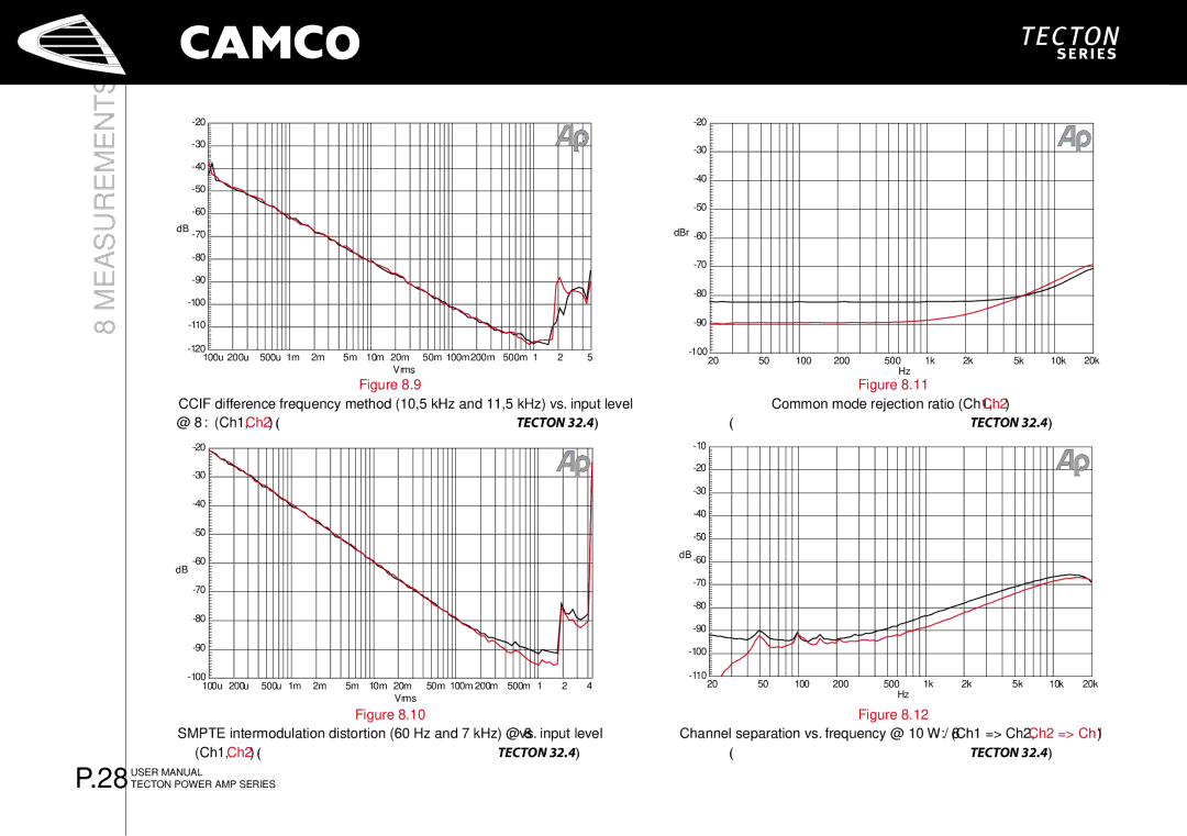
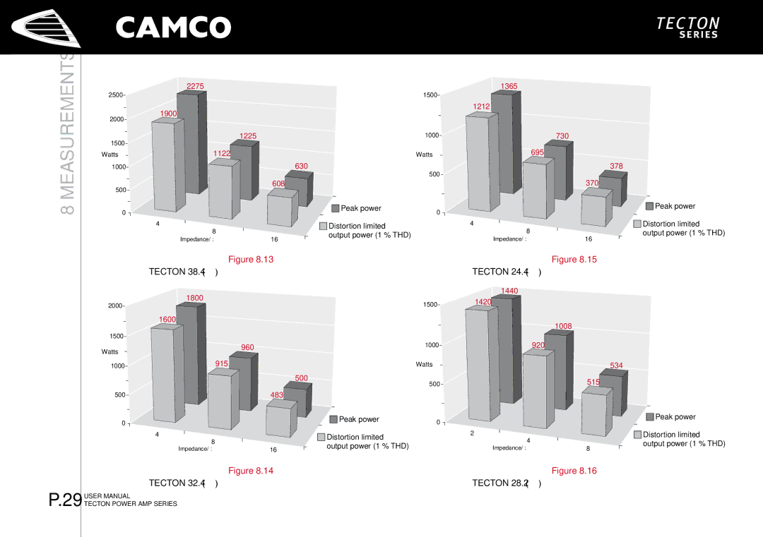
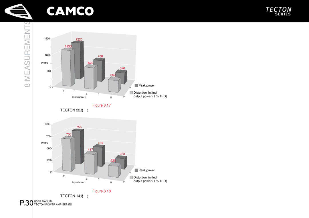
Contents Page Page Information for USE for Important Safety Instructions Important Safety InstructionsExplanation of Symbols / Safety Safety Manufacturers Address EC Declaration of ConformityManufacturers Name Declares that the product with the model nameContents Welcome Welcome to CamcoUnpacking Tecton is a Class-H power amplifier with a power output AmplifierFacilities Tecton The Front Tecton The RearFactory Settings Front panelInstallation Mains SupplyOn/Off Switch MountingMode Indicators CoolingGround Lift Mode Selector Wiring 1 E.U.I. and XLR ConnectionStereo Operation, 2 Channel Operation Mono-Bridge Operation One-channel mono bridged operationParallel-Mono Operation Operation Speakon ConnectionGain Selector Controls Volume ControlLimiter Switch Gain and Input SensitivityIndicators Output Current LEDs Signal LEDs multifunctionalSOA Protection Power Amp Protection Systems 4.3.1 Clip LimiterClip LEDs DC ProtectionMains Failure Detection Mains Protections Inrush Current LimitationMains Over Voltage Detection Fuse ProtectionWhat Are The Possibilities Using The E.U.I.2? OptionsE.U.I.2 Extended User Interface Troubleshooting Signal to Noise-Ratio SpecificationOutput Power Power Consumption @ 2301400 W @ 2 Ω 1100 W @ 2 Ω 670 W @ 2 Ω Output Connectors IndicatorsInput Connectors Dimensions WxHxDMeasurements Measurements of a typical performanceMeasurements of a typical performance of Tecton Ch1, Ch2 Measurements of a typical performance of Tecton Tecton 24.4 Measurements of a typical performance Tecton 14.2 Measurements of a typical performance Warranty Information Owner’s Information Expired WarrantyNature Of Problem Shipping AddressMaintenance Information DECOMISSIONINGINFORMATION/12Decomissioning Telephone Company InformationMailing Address Facsimile