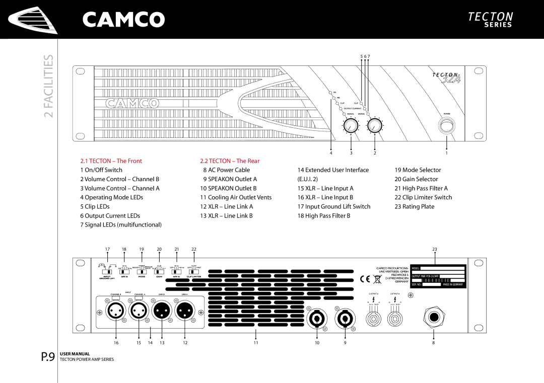
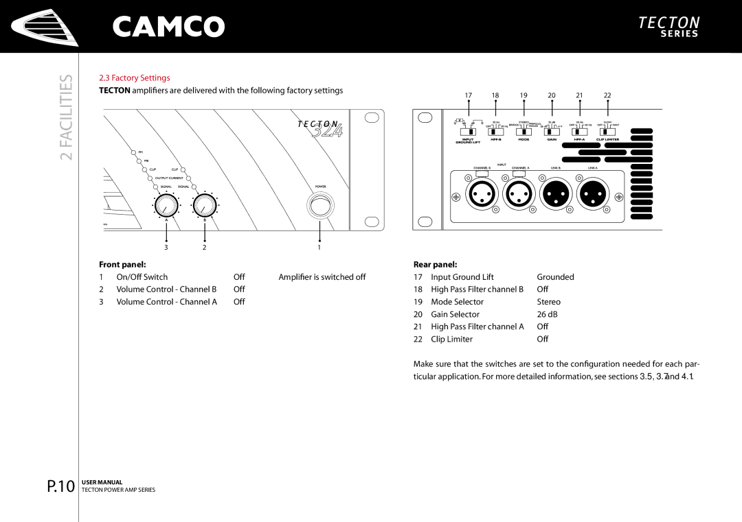
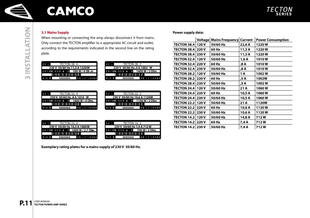
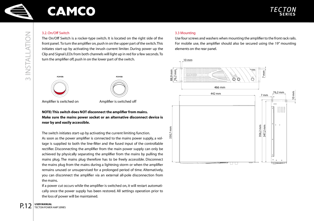
Camco P.4 Series, P.9 Series manual Stereo Operation, 2 Channel Operation, Parallel-Mono Operation

Page 17

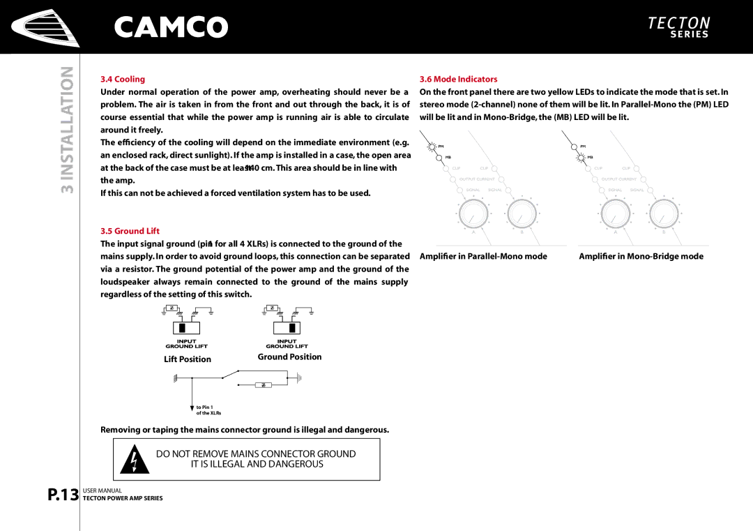
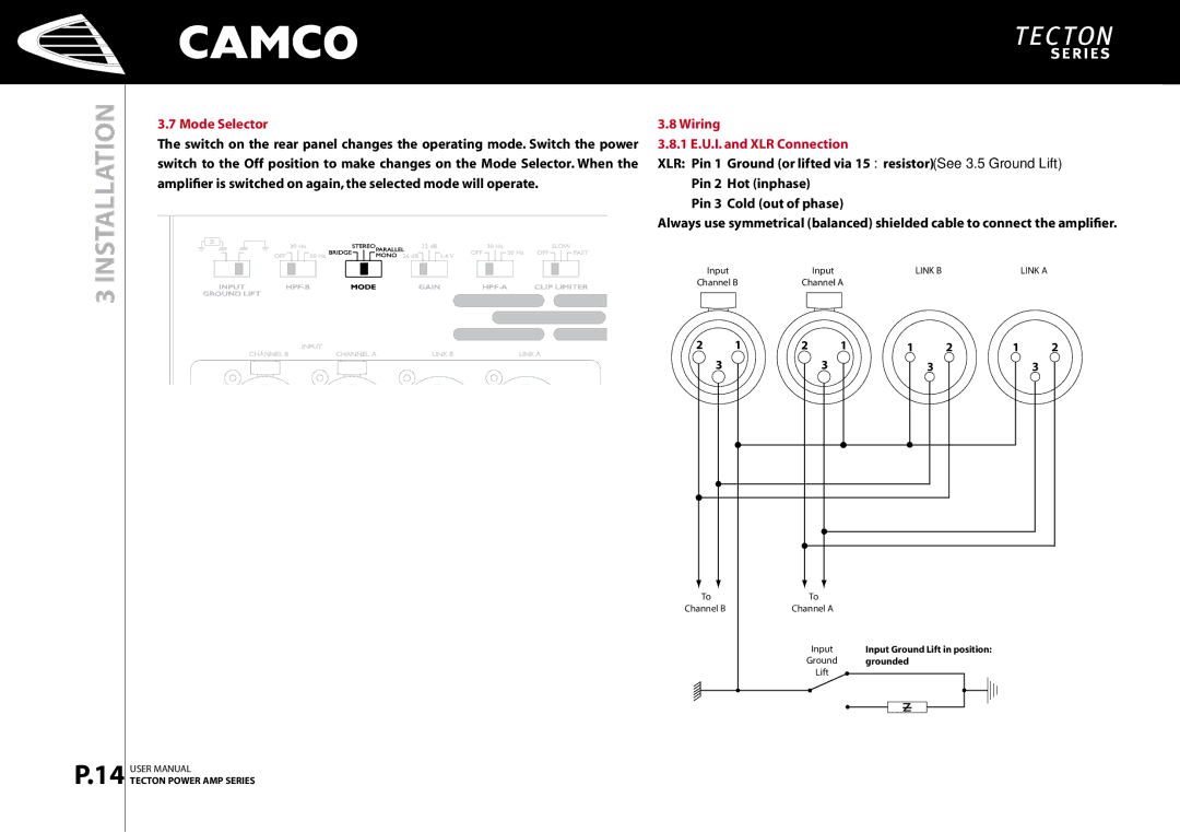
3.8.2 Stereo Operation, 2 Channel Operation

Two fully independent amplifier channels (normal operating mode).

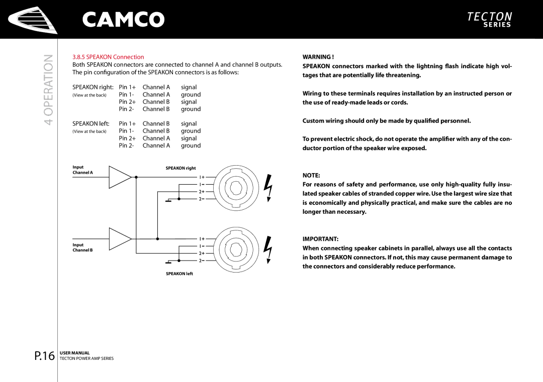
3.8.4 Mono-Bridge Operation One-channel mono bridged operation.

TECTON

A (L)

B (R)

Z *Zmin

Z *Zmin

TECTON

A

Z 2 *Zmin

3 INSTALLATION

P.15

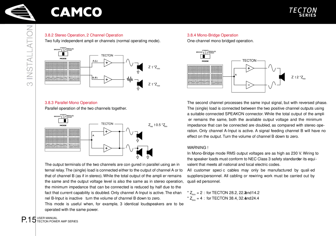
3.8.3 Parallel-Mono Operation

Parallel operation of the two channels together.

TECTON

Zres

0.5 *Zmin


A


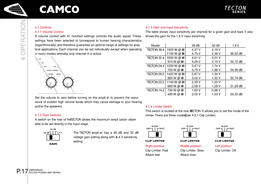
The output terminals of the two channels are configured in parallel using an in- ternal relay.The (single) load is connected either to the output of channel A or to that of channel B (as if in stereo). While the total output of the amplifier remains the same and the output voltage level is also the same as in stereo operation, the minimum impedance that can be connected is reduced by half due to the fact that current capability is doubled. Only channel A-Input is active. The chan- nel B-Input is inactive – turn the volume of channel B down to zero.

This mode is useful when, for example, 3 identical loudspeakers are to be ­operated with the same power.

USER MANUAL

TECTON POWER AMP SERIES

The second channel processes the same input signal, but with reversed phase. The (single) load is connected between the two positive channel outputs using a suitable connected SPEAKON connector. While the total output of the ampli- fier remains the same, both the available output voltage and the minimum impedance that can be connected are doubled, as compared with stereo ope­ ration. Only channel A-Input is active. A signal feeding channel B will have no effect on the output.Turn the volume of channel B down to zero.

WARNING !

In Mono-Bridge mode RMS output voltages are as high as 230 V. Wiring to the speaker loads must conform to NEC Class 3 safety standards or its equi- valent that meets all national and local electric codes.

All customer specific cables may only be manufactured by qualified suppliers/personnel. All cabling or rewiring work must be carried out by qualified personnel.

*Zmin = 2 Ω for TECTON 28.2, 22.2 and 14.2

*Zmin = 4 Ω for TECTON 38.4, 32.4 and 24.4
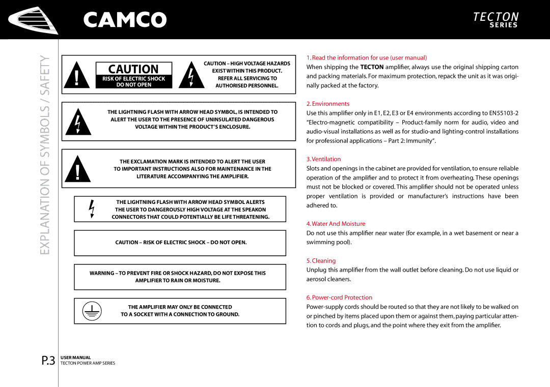
Image 17
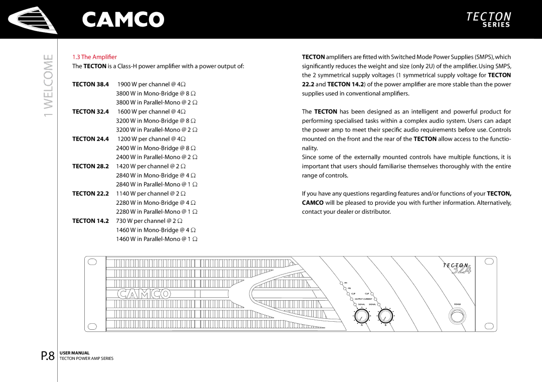
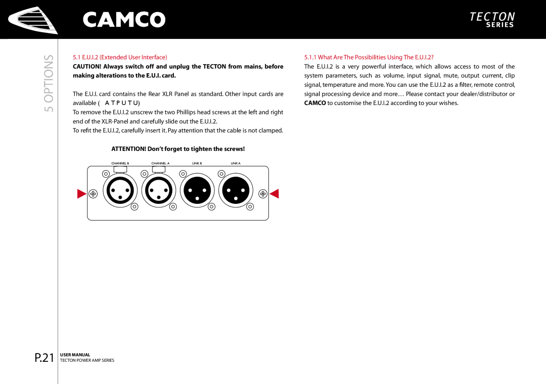
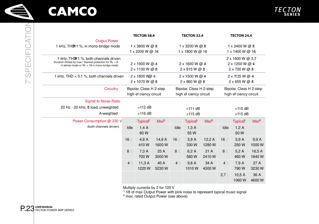
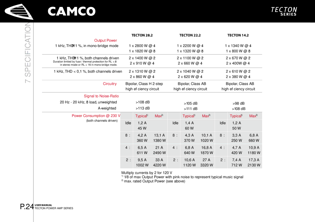
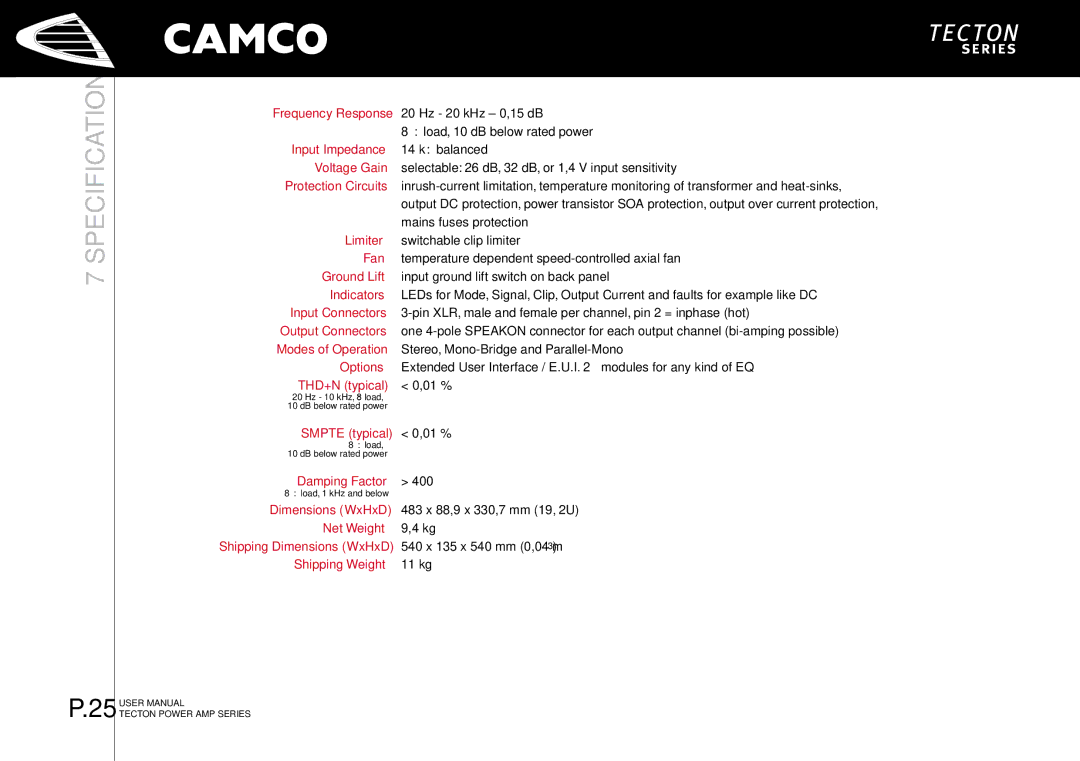
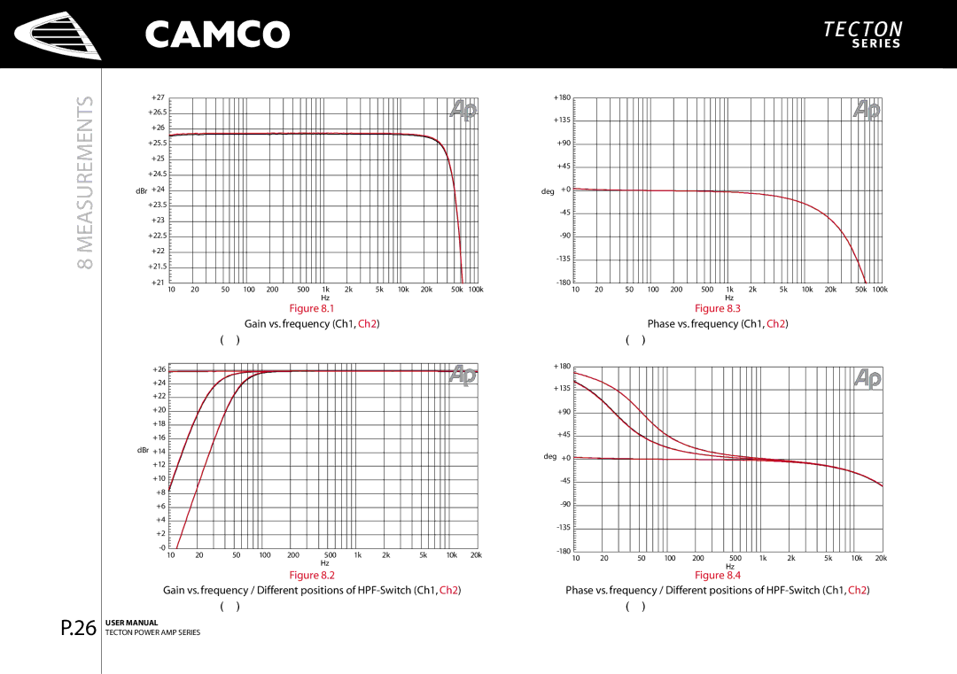
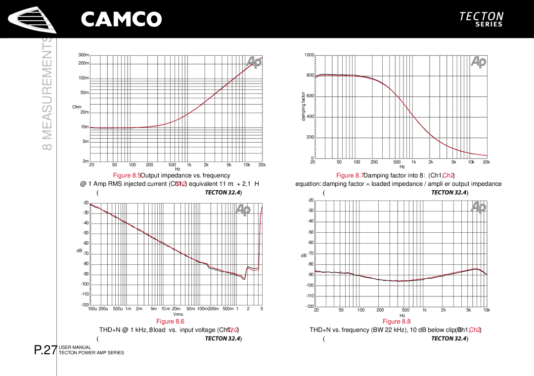
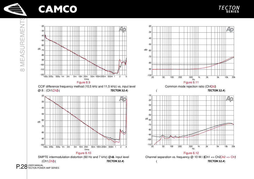
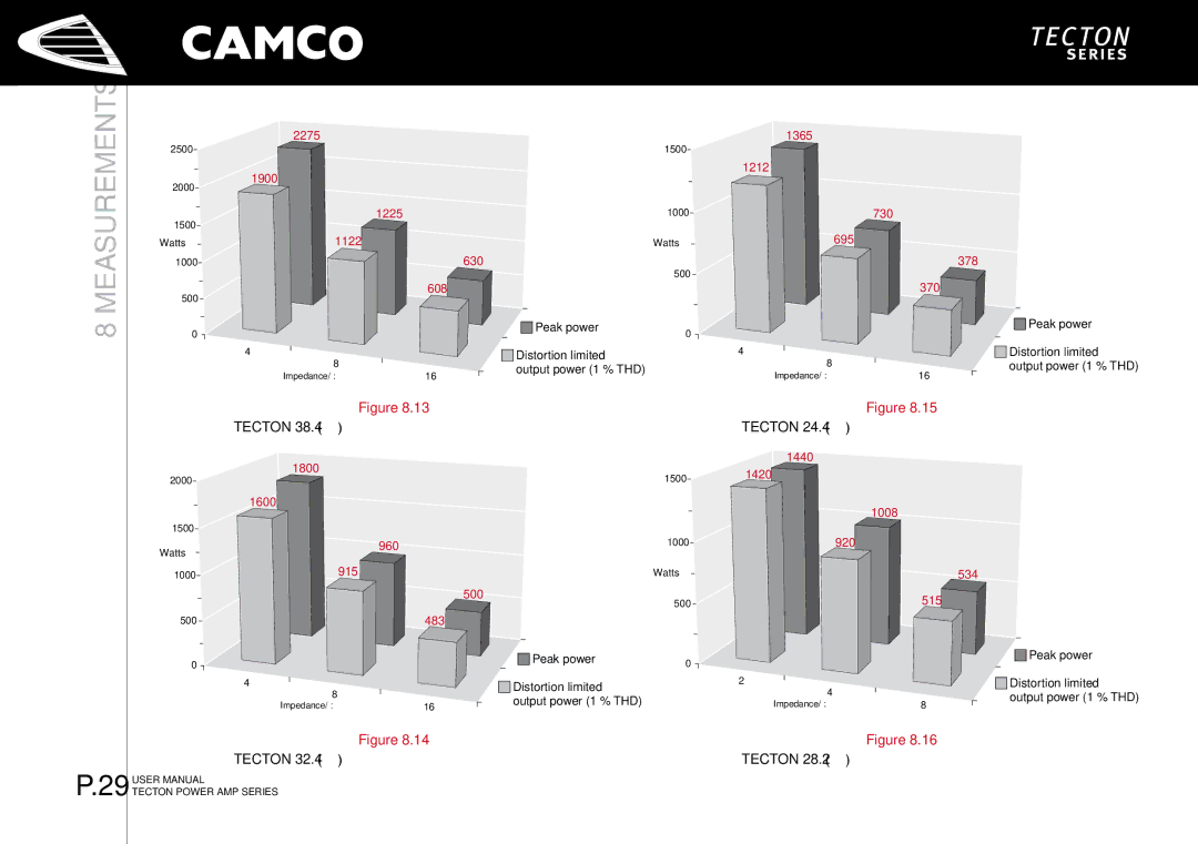
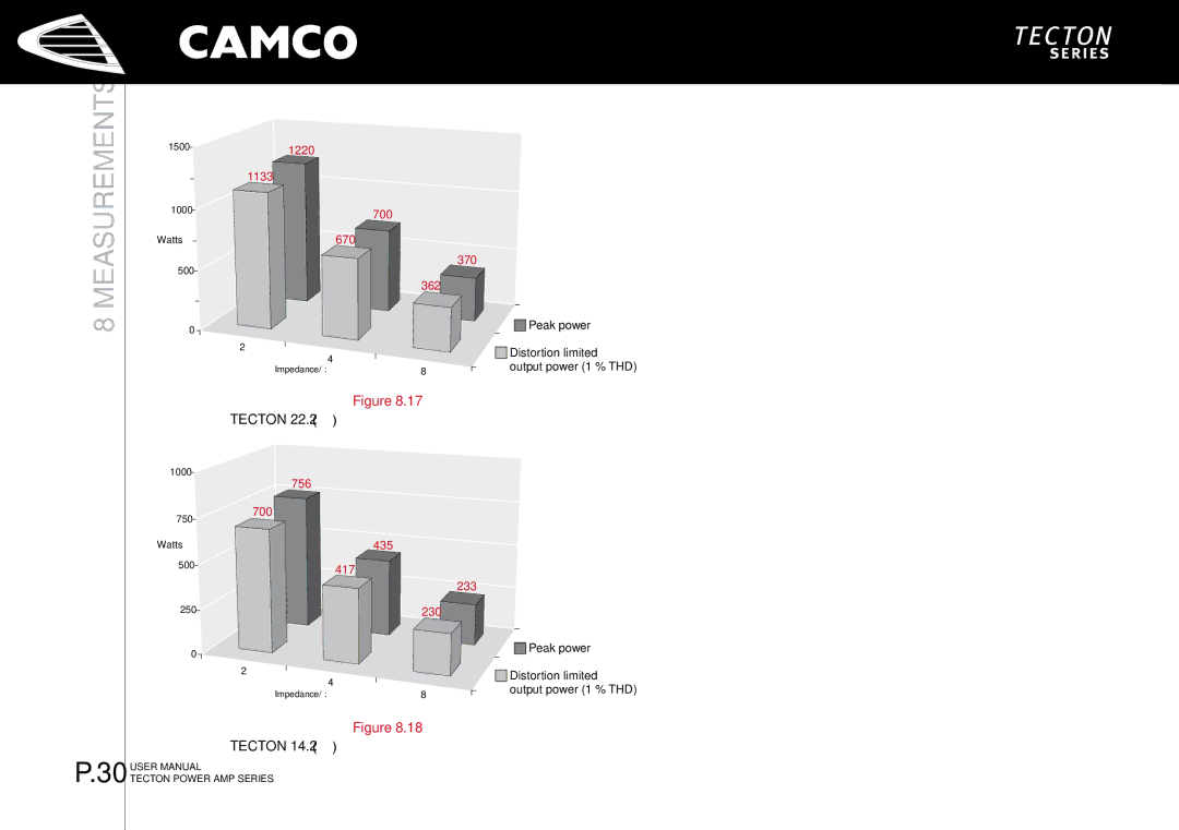
Contents Page Page Information for USE for Important Safety Instructions Important Safety InstructionsExplanation of Symbols / Safety Safety Manufacturers Name EC Declaration of ConformityManufacturers Address Declares that the product with the model nameContents Unpacking WelcomeWelcome to Camco Amplifier Tecton is a Class-H power amplifier with a power outputTecton The Front Tecton The Rear FacilitiesFront panel Factory SettingsMains Supply InstallationMounting On/Off SwitchGround Lift Mode IndicatorsCooling Wiring 1 E.U.I. and XLR Connection Mode SelectorParallel-Mono Operation Stereo Operation, 2 Channel OperationMono-Bridge Operation One-channel mono bridged operation Speakon Connection OperationLimiter Switch Controls Volume ControlGain Selector Gain and Input SensitivitySignal LEDs multifunctional Indicators Output Current LEDsClip LEDs Power Amp Protection Systems 4.3.1 Clip LimiterSOA Protection DC ProtectionMains Over Voltage Detection Mains Protections Inrush Current LimitationMains Failure Detection Fuse ProtectionE.U.I.2 Extended User Interface What Are The Possibilities Using The E.U.I.2?Options Troubleshooting Output Power SpecificationSignal to Noise-Ratio Power Consumption @ 2301400 W @ 2 Ω 1100 W @ 2 Ω 670 W @ 2 Ω Input Connectors IndicatorsOutput Connectors Dimensions WxHxDMeasurements of a typical performance MeasurementsMeasurements of a typical performance of Tecton Ch1, Ch2 Measurements of a typical performance of Tecton Tecton 24.4 Measurements of a typical performance Tecton 14.2 Measurements of a typical performance Warranty Information Nature Of Problem Expired WarrantyOwner’s Information Shipping AddressDecomissioning Maintenance InformationDECOMISSIONINGINFORMATION/12 Mailing Address Company InformationTelephone Facsimile