HOSE AND REGULATOR:
Your grill is equipped with a Type 1 connection device with the following features:
1.The system will not allow gas flow from the cylinder until a positive connection to the valve has been made.
Note: The cylinder valve and all grill burner knobs must be turned OFF before any connection is made or removed.
2.A regulator flow limiting device, when activated, restricts the flow of gas to 10 cubic feet per hour. If the flow limiting device is activated, perform Regulator Resetting Procedure.
Note: If your grill will not get hot enough to cook, the flow limiting device may have been activated.
CONNECTING HOSE AND REGULATOR:
1. Inspect the propane tank valve rubber seal for cracks, wear or deterioration prior to use. A damaged rubber seal can cause a gas leak, possibly resulting in an explosion, fi re or severe bodily harm. Do not use a propane tank with a damaged rubber seal.
2. Attach or detach regulator to the LP gas cylinder only when cylinder is at rest in tank holder.
3. Check that the cylinder valve is closed by turning the knob clockwise.
4. Check that the grill’s burner control knobs are in the “OFF” positions.
5. Visually inspect the hose assembly prior to each use for evidence of damage, excess wear, or deterioration. If found, replace the assembly before using your grill. Only the manufacturer’s supplied replacement should be used.
6. Remove the protective plastic cap from the cylinder valve.
7. Check that the hose does not contain kinks, does not contact sharp edges, and does not contact surfaces that may become hot during use.
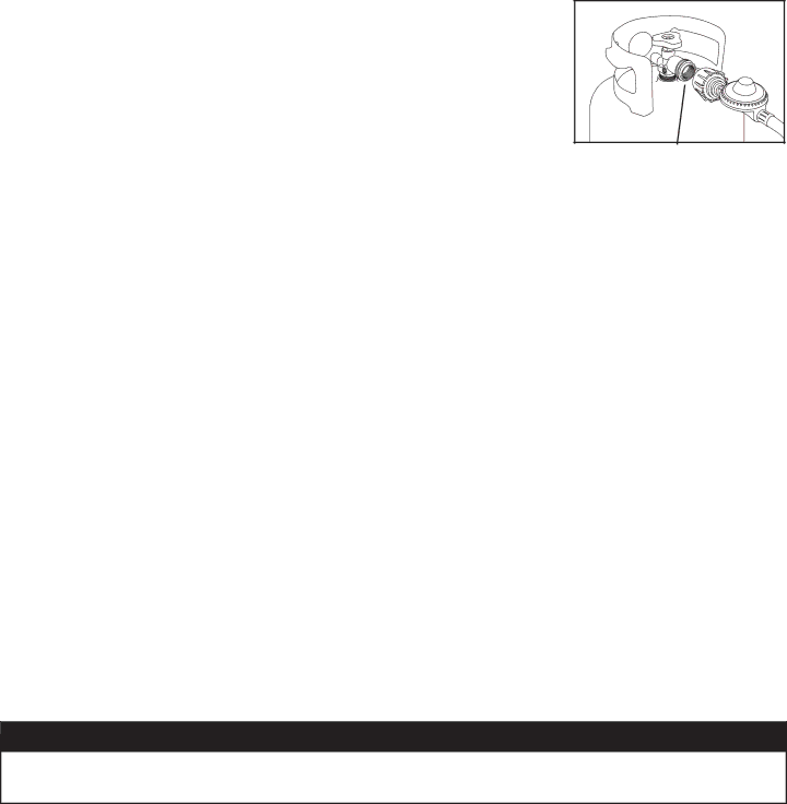
8. Hold regulator and insert the brass nipple into the LP cylinder valve outlet. Ensure that the device is centered properly.
9. Turn the large coupling nut clockwise by hand and tighten to a full stop. Take care not to cross thread the coupling nut onto the cylinder valve. Do not use tools to tighten connection.
Note: If you are unable to make the connection, repeat Steps 7 and 8.
10. Leak check all fittings before lighting your grill. See section on “Leak Testing” in this manual.
REGULATOR RESETTING PROCEDURE:
If your grill will not get hot enough to cook, the flow limiting device may have been activated. Mini Reset:
1.Turn ALL burner control knobs to “OFF”, turn off the cylinder valve. Wait one minute. Slowly turn cylinder valve ON and relight grill. If burner flame is higher and grill heats up properly – proceed with cooking.
Full Reset:
1.Turn ALL burner control knobs to “OFF”, turn off the cylinder valve. Disconnect hose and regulator from cylinder. Wait two minutes, reattach hose and regulator and perform leak test.
LEAK TESTING:
![]() WARNING
WARNING
•Never use your grill without leak testing all gas connections, hoses and propane tank. Follow the section on “Leak Testing” in this manual for proper procedures.
7