Gentek 3950302, 3940200, 3950320, 3950202, 3940421, 3940320, 3940402, 3950222, 3940300 Acceptance

Page 54

Chapter 6: Maintaining Your Filtered Enclosure

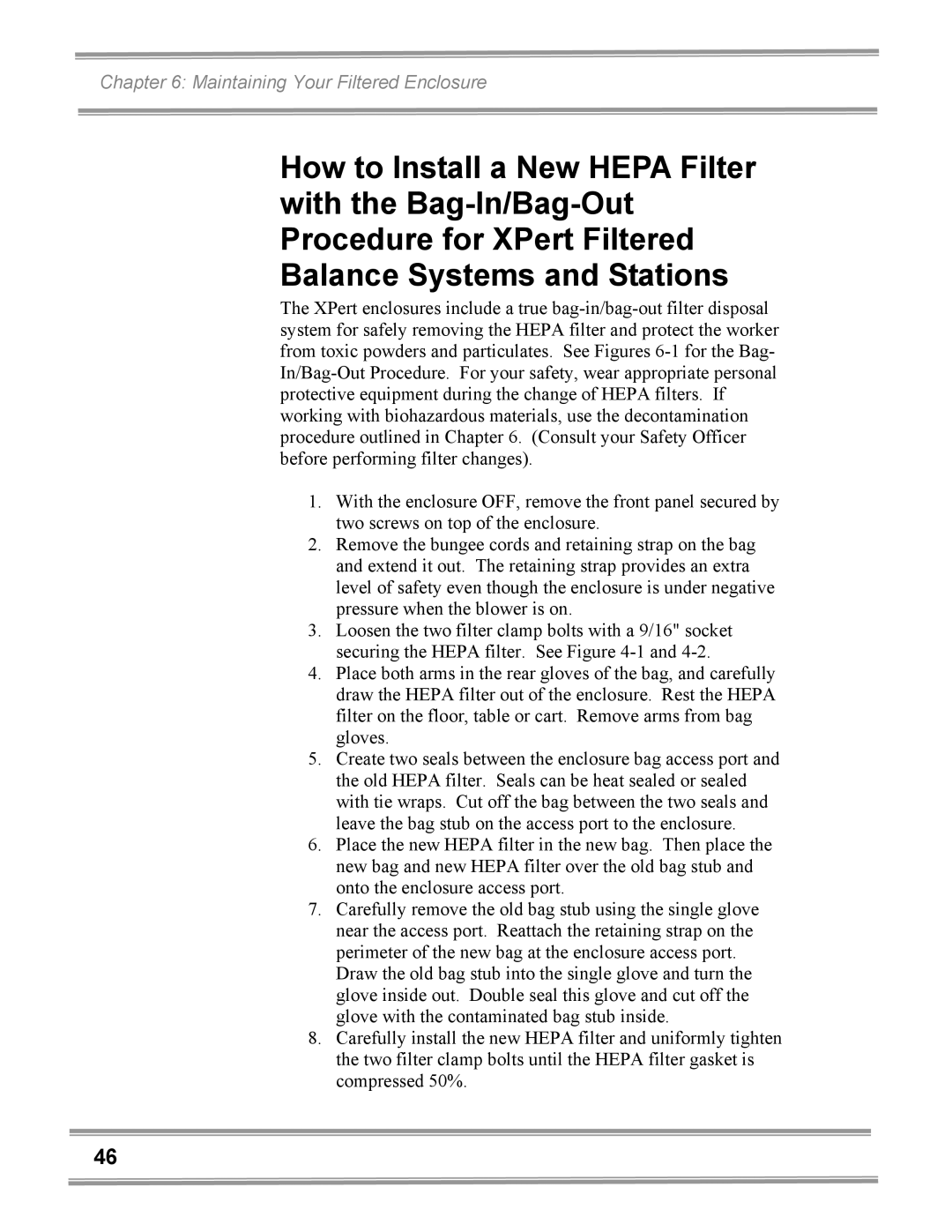
8.If necessary, adjust the speed control of the enclosure to maintain the following airflows at 90 fpm; 2' (130cfm), 3' (200 cfm, 4' (265 cfm.)

9.Position the aerosol generator discharge in the intake of the baffle inside the enclosure.

10.Start the aerosol generator (Pressure to be +/- 1 PSIG). Ensure that one Laskin nozzle is in the “open” position.

11.Allow the generator to operate for a minimum of 15 seconds. For all integral motorized impeller models, scan the downstream exhaust side of the HEPA filter by passing the sampling nozzle of the gun in slightly overlapping strokes over the entire surface the filter, with the sampling port not more than 1 inch from the surface of the filter media. Scan the entire periphery of the filter and the gasket between the filter frame and the enclosure frame. Scanning shall be done at a traverse rate of not more than 2 inches per second.

NOTE: For the XPert Filtered Balance Station, place the sampling nozzle in the center of the remote blower exhaust.

Acceptance

Aerosol penetration shall not exceed 0.01 percent measured by the photometer

Setting the Inflow Face Velocity with the Speed Control Adjustment

1.Remove the front panel by loosening the (2) Phillips screws on top that secure the front panel.

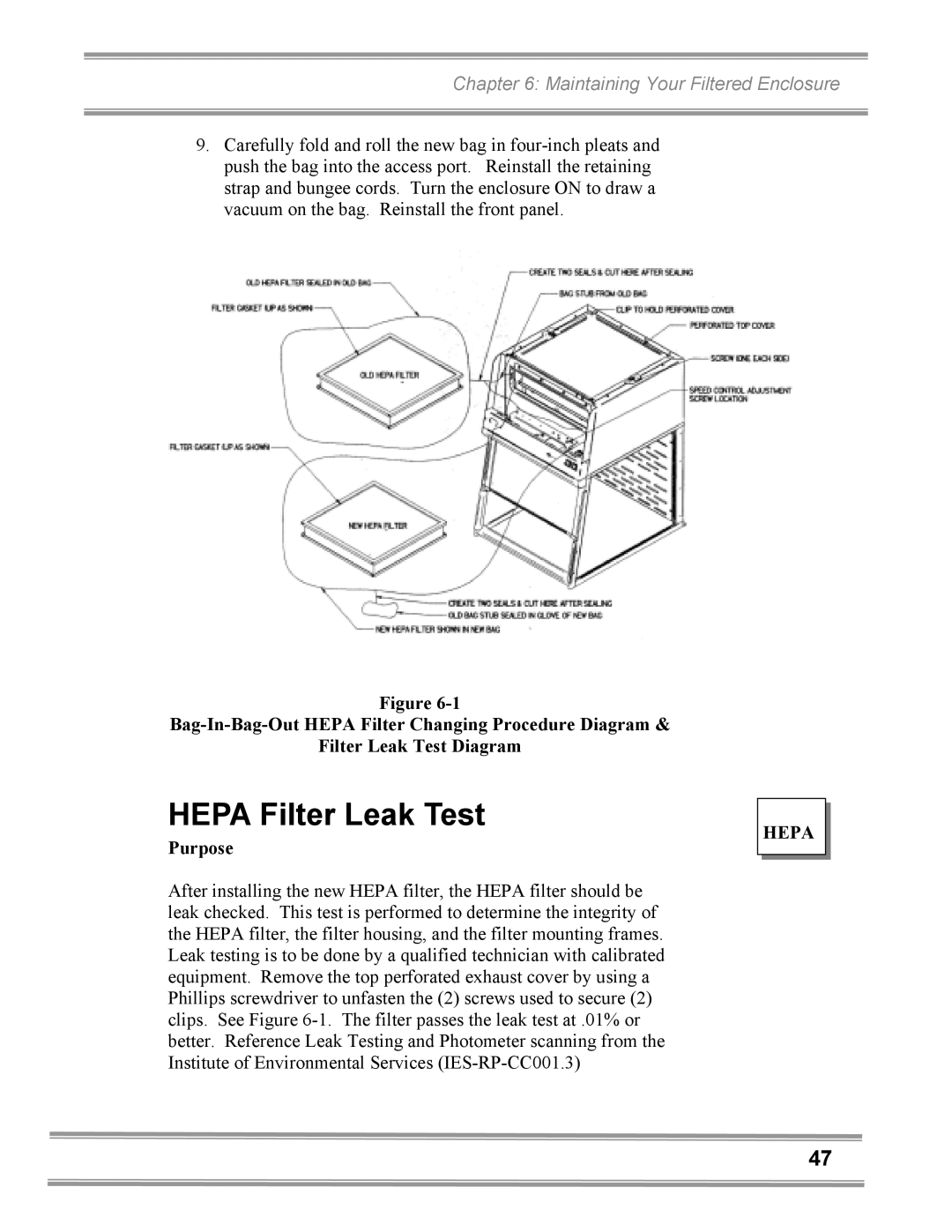
2.The speed control is located on the electrical subassembly located behind the switched control panel and below the front panel. See Figure 6-1.

3.Adjust the speed control with a small Phillips screwdriver by turning the screw counterclockwise to increase blower speed or clockwise to decrease the blower speed. The speed control is very sensitive, so proceed with caution.

4.Measure the inflow velocity per the averaging technique outlined in Chapter 3 and adjust the speed control slowly for the desired speed. Allow the speed to stabilize and re- measure the inflow velocity to confirm.

5.Replace the front panel and tighten the screws.

XPERT

FILTERED BALANCE SYSTEM

49
Image 54
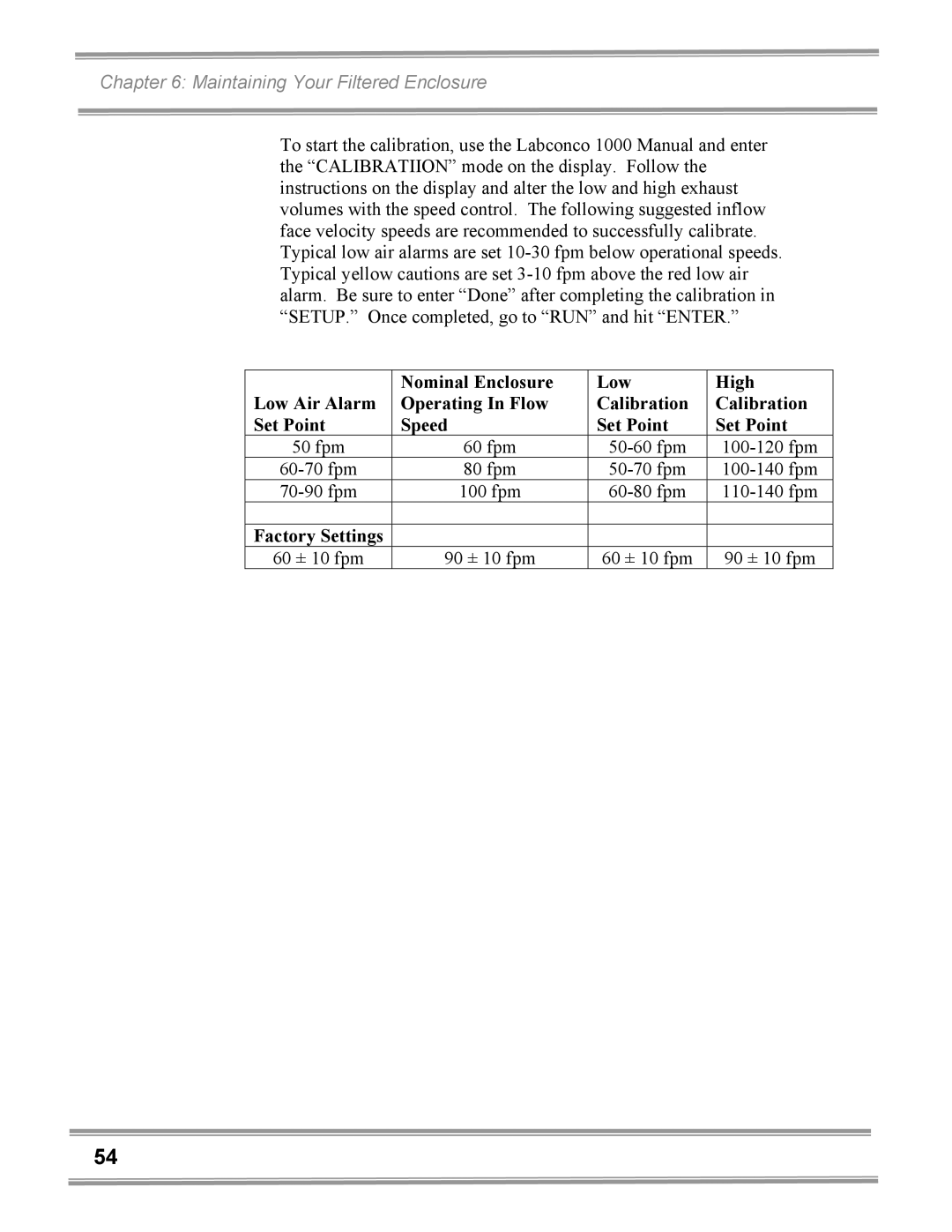
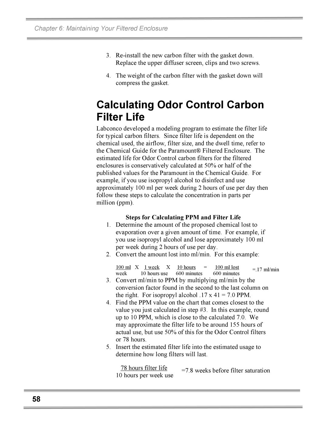
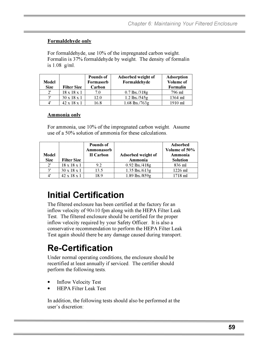
Contents User’s Manual USA Warranty Able Ontents PrerequisitesMaintaining Your Filtered Enclosure Chapter Introduction Introduction About This Manual Typographical Conventions Chapter Prerequisites Temperature Variation Requirements Support, Vibration and Movement RequirementsHumidity and Static Electricity Requirements Background on Electrostatics or Static ElectricityLocation and Air Current Requirements Exhaust and Blower RequirementsSurface Resistivity Table XPert Station Electrical Requirements Space RequirementsChapter Getting Started Lift by the front air foilUnpacking the Enclosure Do not move the enclosure by tilting it onto a hand truckWork Surface Specifications Work Surface and Hepa Filtered Enclosure InstallationFiltered Enclosure Installation XPert Station Getting Started Getting Started Installation of Hepa Filters Accessory Odor Control Carbon Carbon Filters Accessory for Odor Control onlyHepa Filters Filter Type Appropriate Use 115V ModelsGetting Started Set the Face Velocity with the Speed Control Adjustment Validating the Vented EnclosureSealing the Filtered Enclosure to the Work Surface Chapter High Performance Features and Safety Precautions High Performance FeaturesHigh Performance Features and Safety 1510 Hepa Filtered Enclosure Airflow Diagram High Performance Features and Safety High Performance Features and Safety High Performance Features and Safety High Performance Features and Safety Safety Precautions High Performance Features and Safety High Performance Features and Safety High Performance Features and Safety Routine Daily Work Procedures PlanningWork Techniques Start-upLoading Materials and Equipment Final PurgingSuitable Applications Hepa Filter Applications Suitability and GuidelinesShutdown Odor Control Carbon Filter Applications sold as an accessory Definition of Terms Appropriate Chemicals for Odor Control Carbon Filters Chemical Carcinogen Use with Odor Control Carbon Filters Prohibited Acid UseBalance Station, which uses a remote blower Chapter Maintaining Your Filtered Enclosure Routine Maintenance Schedule WeeklyMonthly or more often as required Determination of when to Replace Hepa Filters DecontaminationAnnually Maintaining Your Filtered Enclosure Hepa Filter Leak Test PurposeMineral oil Catalog #1491400 Acceptance Labconco Airflow Monitor / Airflow Switch Operation Calibrate and Operate the Airflow MonitorsGuardian Airflow Monitor LED Monitor Enclosure Operating In-Flow Alarm Condition Set Point Speed CalibrationGuardian Airflow Monitor LED with Airflow Switch Guardian Digital 1000 Airflow MonitorOperation Digital 1000 CalibrationFactory Settings Guardian Digital 1000 Airflow Monitor Maintaining Your Filtered Enclosure Odor Control Carbon Filter Replacement Procedure See Calculating Odor Control Carbon Filter Life Steps for Calculating PPM and Filter LifeFormaldehyde only Initial CertificationRe-Certification Ammonia onlyFluorescent Light Replacement Motorized Impeller ReplacementMotorized Impeller Replacement Speed Control Replacement Chapter Accessorizing Modifying Your Filtered Enclosure Work SurfacesAdd appropriate Front Panel with cutout to mount Digital Airflow MonitorExhaust Transition Kits for Ducting to Outside Part Description Remote BlowersHepa Filter Bag-In/Bag-Out Bag Accessory Filters Hepa FilterExhaust Dampers Odor Control Carbon FilterStorage Cabinets Utility Shelf KitAccessorizing and Modifying your Filtered Enclosure Chapter Troubleshooting Servicer Operating LOG Problem Cause Corrective ActionTroubleshooting Problem Cause Corrective Action Service Operating Record Log Date CommentsAppendix a Filtered Enclosure Components Replacement Parts Qty Part Number Description Qty Part Number Description Long Use for XPert System and XPert Station Use for XPert System, XPert Station, Digital Monitor and Bag Appendix B Dimensions Exhaust Options Figure B-1 XPert Filtered Balance System Figure B-2 XPert Filtered Balance Station Appendix B Dimensions and Exhaust Options Appendix C Filtered Enclosure Specifications Environmental ConditionsAppendix C Filtered Enclosure Specifications Appendix C Filtered Enclosure Specifications Appendix C Filtered Enclosure Specifications Appendix C Filtered Enclosure Specifications Appendix C Filtered Enclosure Specifications Ppendix Uick Hart Iltered Nclosures Model SizeNon-mandatory recommendations from Prudent Practices Appendix E References Nfpa 30 2000 Flammable and Combustible Liquids Code General References Laboratory Safety, Principles and Practices, American Page USA