DKS Enterprises 1808, 1803, 1802, 1810 owner manual Installation Guidelines ALL Systems

Page 9

SECTION 1 - INSTALLATION

Order your telephone line at least two weeks prior to the planned installation date. This will assure that a phone line is available when the unit is installed. The telephone company will require the following information from you:

Type:

Touch Tone, Loop Start

Ringer Equivalence:

0.0 A

Jack Type:

RJ11C

FCC Registration (US):

DUF6VT-12874-OT-T

DOC (Canada):

1736 4528 A

Electrical Listing:

Complies with U.L. 294 - ETL Listed

CALLER ID: You may want to consider ordering caller ID blocking from the telephone company for the entry system phone line. Without caller ID blocking, tenants with the proper phone equipment will be able to identify the telephone number that the entry system is installed on. This may or may not be desirable.

1.1INSTALLATION GUIDELINES – ALL SYSTEMS

1.Open the cabinet of the telephone entry system and disconnect the keypad ribbon cable from the main circuit board.

2.Remove the 6-32 x 1/2 round head screws from the upper corners of the circuit board.

3.Remove the circuit board by gently pulling it out of the main terminal edge connector. CAUTION - the circuit board contains static sensitive components. Discharge any static electricity from your hands by touching a proper ground device before removing the circuit board. Place the circuit board where it will not be damaged.

4.Mount the cabinet of the telephone entry system. Be sure that mounting screws do not protrude into the cabinet where they could cause a short on the back of the circuit board. Make any necessary conduit connections.

5.Route wiring into the cabinet. Do not apply any power at this time.

6.Clean out the cabinet. Be sure that all dirt, metal and/or wood debris is removed from the cabinet and that the terminal strip edge connector is clean and free of any loose particles.

7.Re-install the circuit board into the cabinet by gently pushing the circuit board terminals into the edge connector. CAUTION - the circuit board contains static sensitive components. Discharge any static electricity from your hands by touching a proper ground device before removing the circuit board.

8.Secure the circuit board to the cabinet using the screws removed in step 2.

9.Plug the keypad ribbon cable into the circuit board. The cable points down.

9
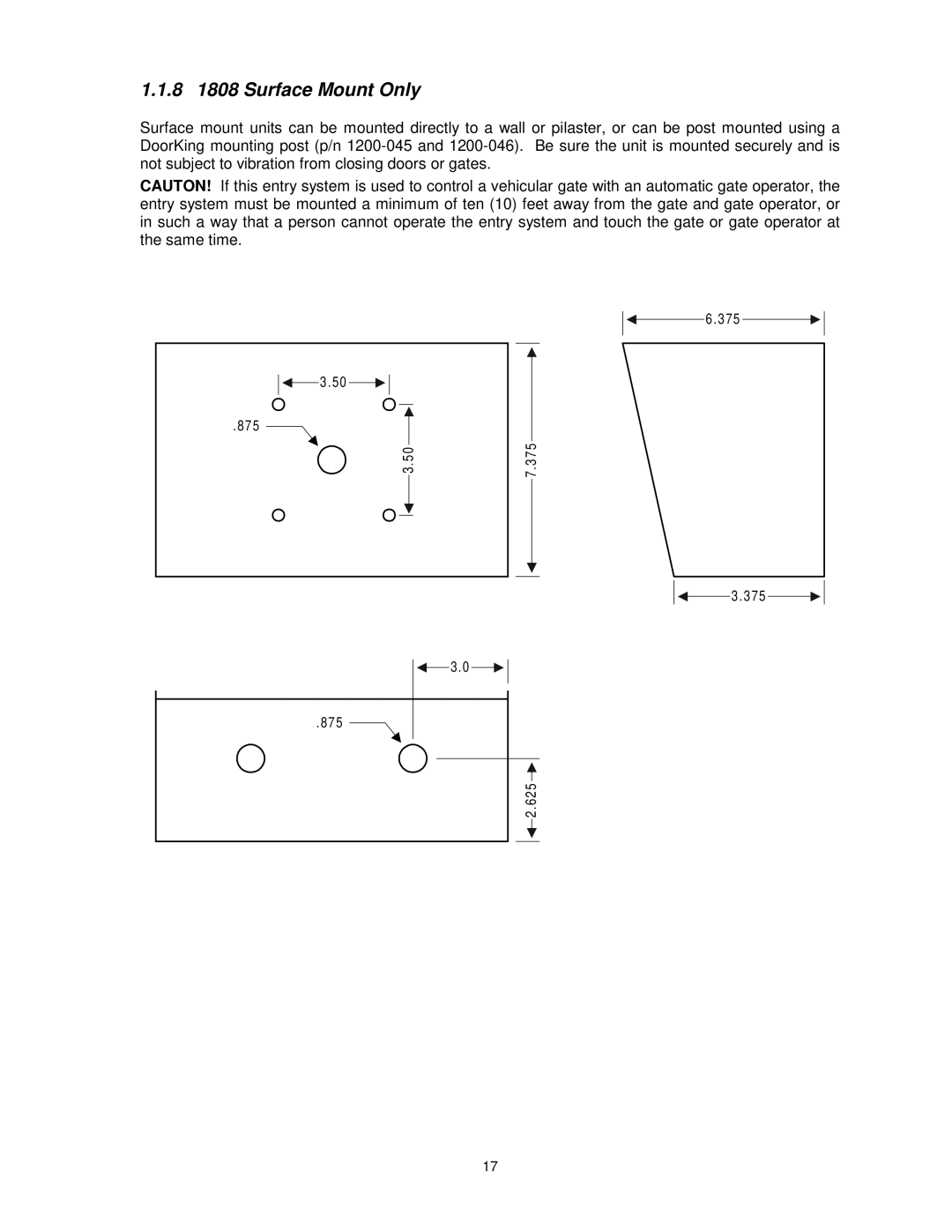
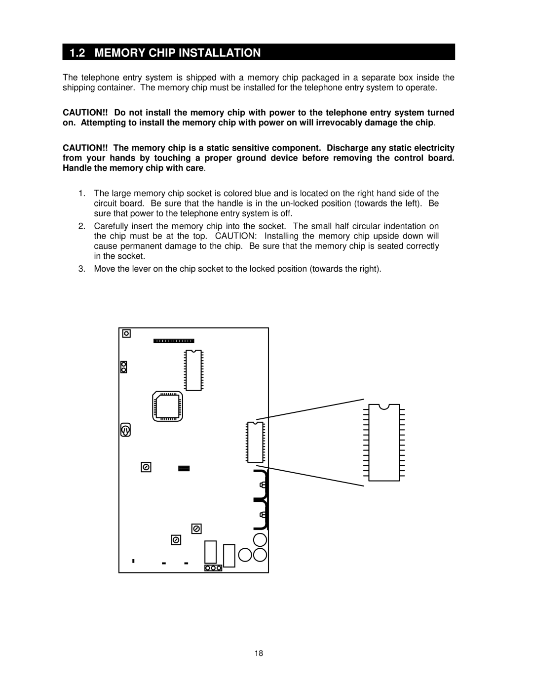
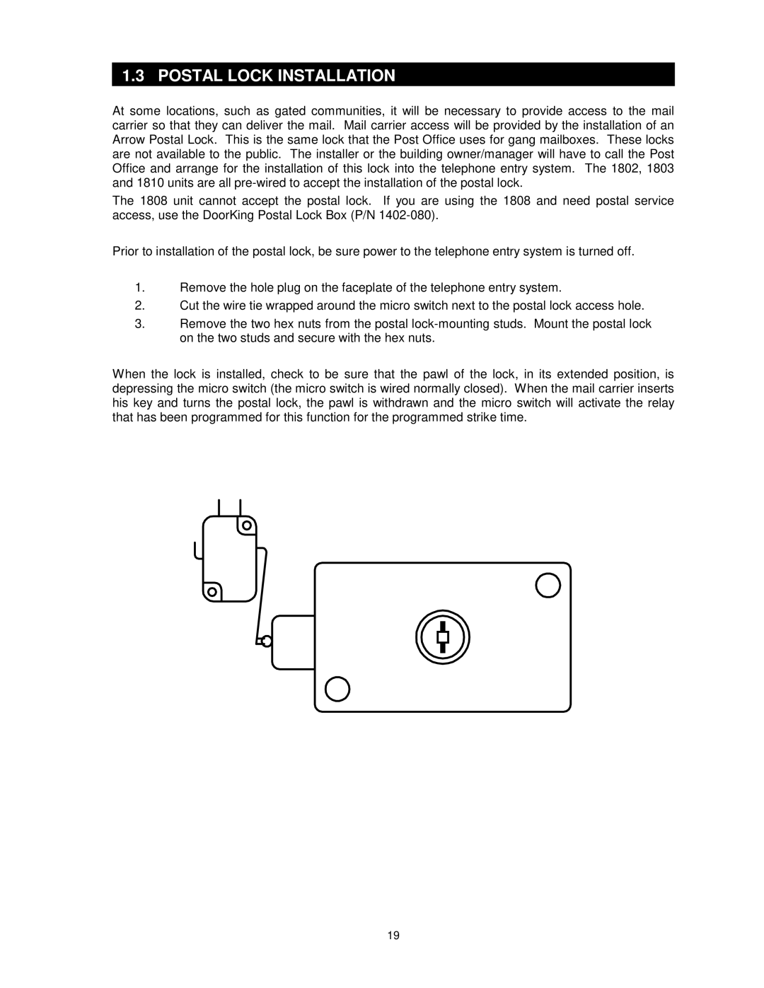
Image 9
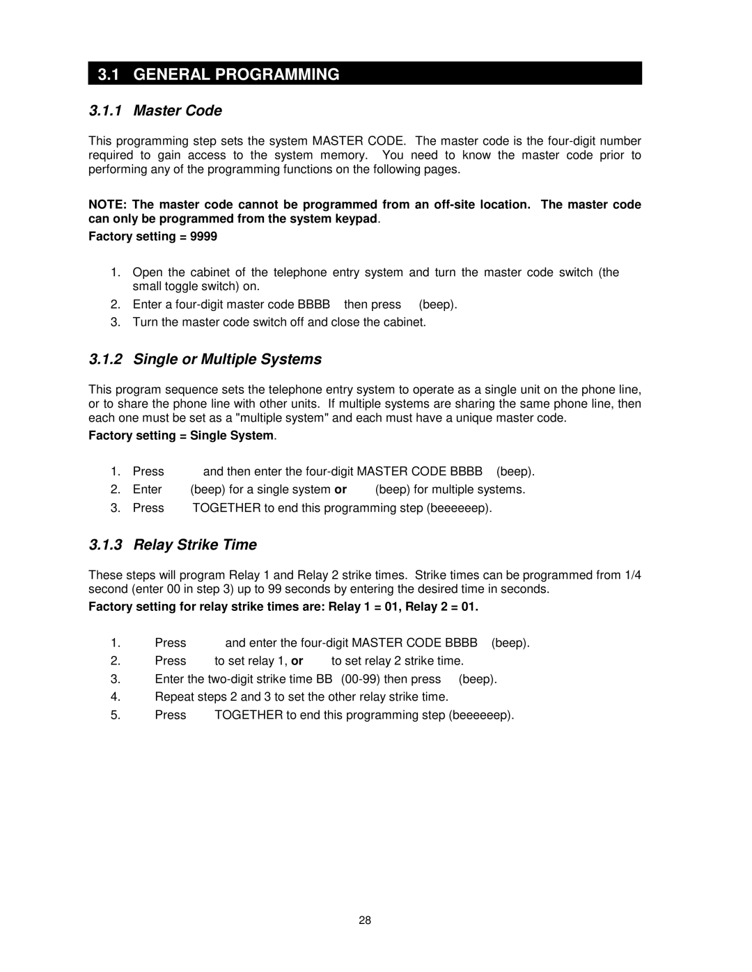
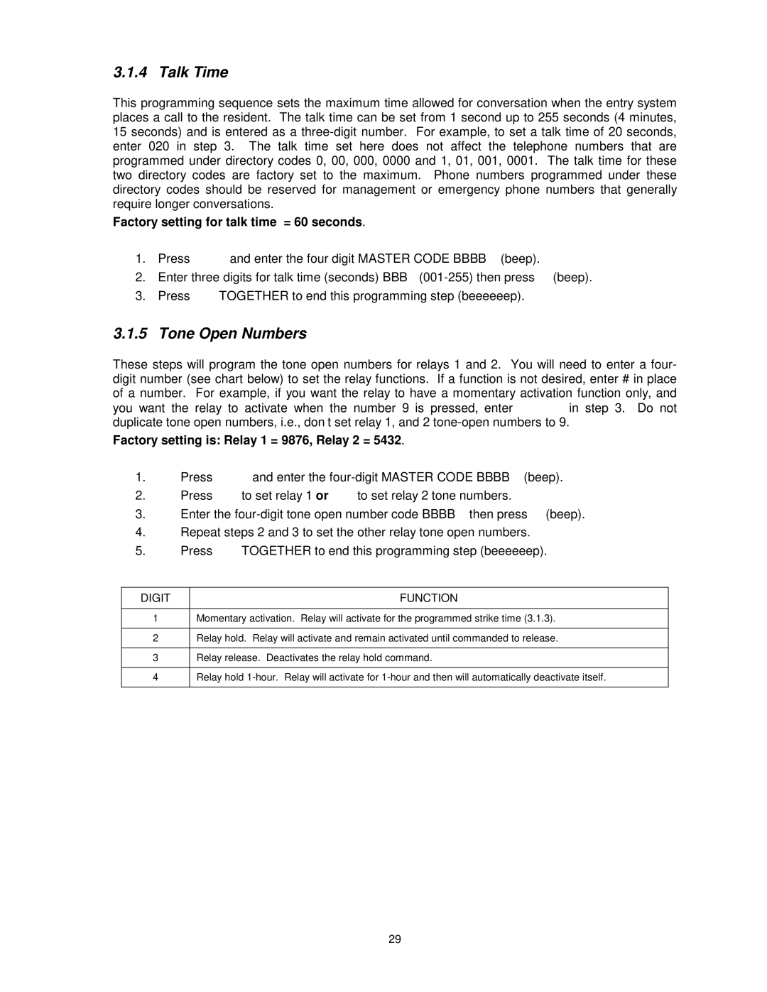
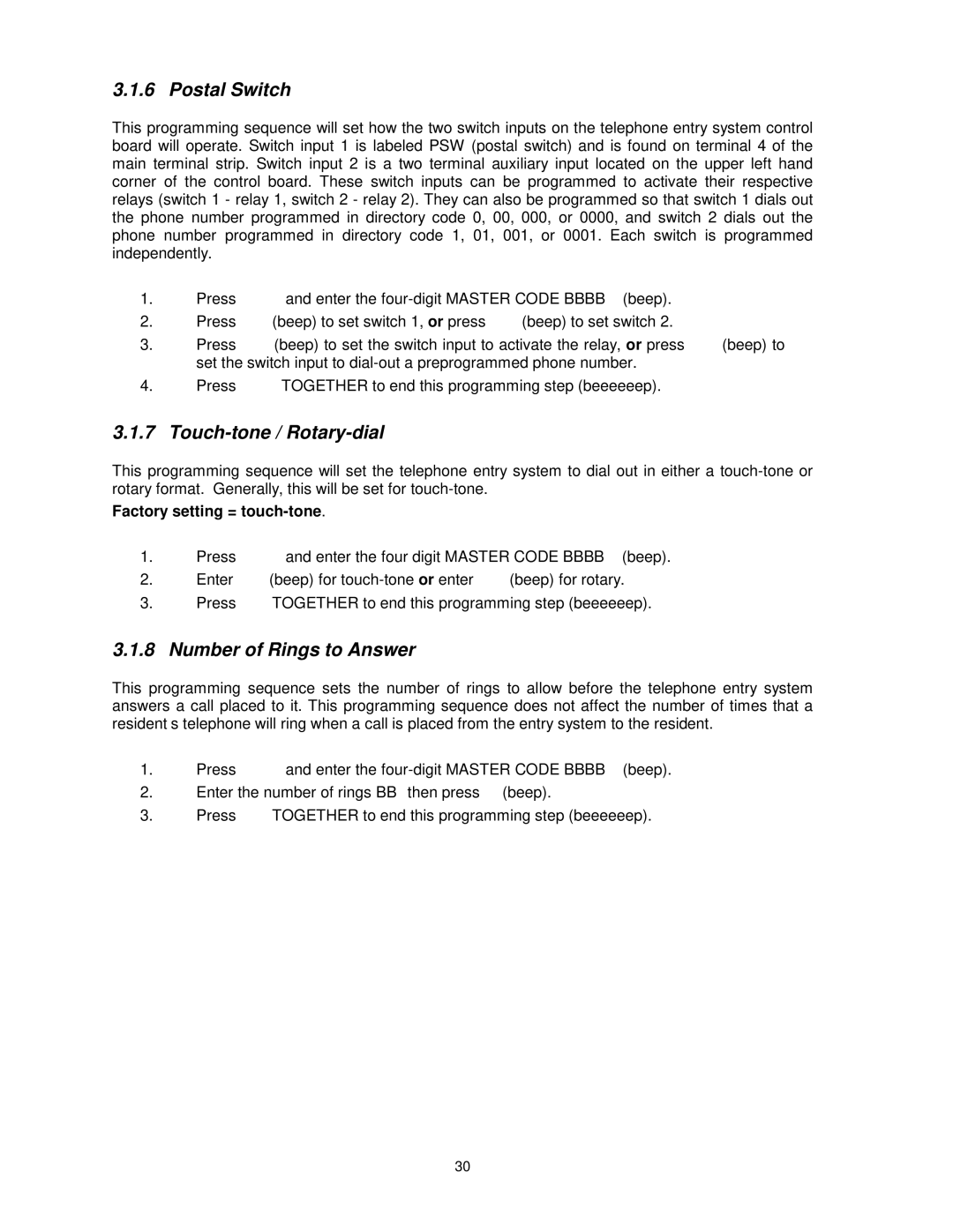
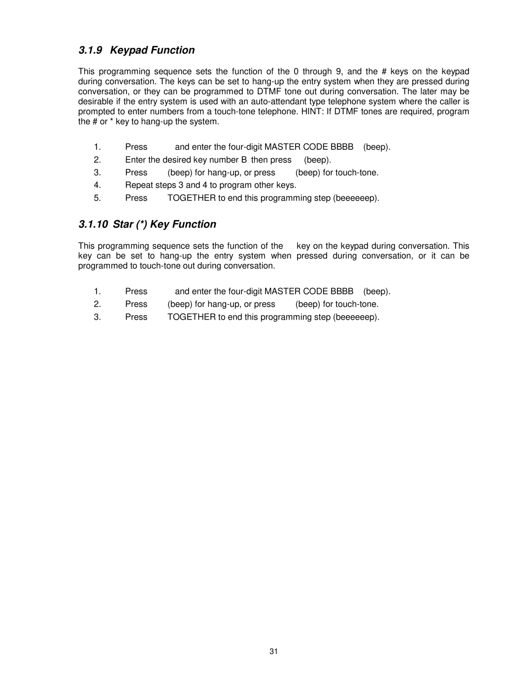
Contents 1802, 1803, 1808, 1810 Telephone Entry Systems Page Use this manual with the following models only Table of Contents Maintenance and Trouble Shooting Listing Important NoticeGeneral Information Features Installation Guidelines ALL Systems InstallationSurface Mount 1803 and 1810 Units Surface Mount 1803 and 1810 Units with Recess Box Flush Mount 1803 and 1810 Units Flush Mount Rough-in Box applies to 1803 and 1810 only Flush Mount Trim Ring use with 1803 and 1810 units only 12.0 375 125 DIA 125 SQ 625 7 1802 Surface Mount Only 8 1808 Surface Mount Only Memory Chip Installation Postal Lock Installation Page Wiring 18AWG Terminal Description Main Terminal DescriptionWiring Description Controlling a Single Door or Gate Relay Wiring TypicalControlling a Gate Operator and Pedestrian Gate or Door Programming from the Keypad Programming from an Offsite LocationProgramming Notes Master Code General ProgrammingSingle or Multiple Systems Relay Strike TimeTone Open Numbers Talk TimePostal Switch Touch-tone / Rotary-dialNumber of Rings to Answer Star * Key Function Keypad FunctionPhone Number Programming Programming the Directory Code LengthProgramming 7-digit Phone Numbers Programming Area Codes Programming Phone Numbers with Area Code ReferenceDeleting Individual Phone Numbers Delete All Phone Numbers Display / Delete Phone NumbersDisplay Phone Numbers with known Directory Codes Four-Digit Entry Code Programming Entry Code ProgrammingDelete Four-Digit Entry Codes Delete All Four-Digit Entry CodesDelete Five-Digit Entry Codes Five-Digit Entry Code ProgrammingDelete All Five-Digit Entry Codes Five-Digit Entry Code Divide NumberTime Functions Programming Time Clock ProgrammingAutomatic Relay Activation Time Zones Five-Digit Entry Code Time Zone Four-Digit Entry Code Time ZoneFlash Entry Codes Relay 2 Terminals Feedback Speaker VolumeClick Sensitivity Display Contrast 1802, 1803, 1810 onlyMaster Code Switch Ring PinHandset / Hands Free General Instructions Using an Entry CodeGuest Instructions Responding to a Guest CallRemote Programming System AdministratorRemote Relay Activation Relay CheckAuto Relay Time Zone Enable / Disable Entry Code Time Zone Enable / DisableSwitch Input Operation Miscellaneous Operating InstructionsLine Sharing Areas with 10-digit Dialing Connection to a PBXPage Trouble Shooting MaintenanceSympton Possible Solutions Accessories LOG Tables Name Phone Number Directory Code Entry Alternate Area Code Name Phone Number Directory Code Entry Alternate Area Code Resident Instruction Sheet