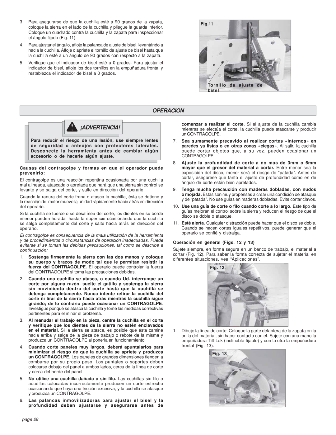
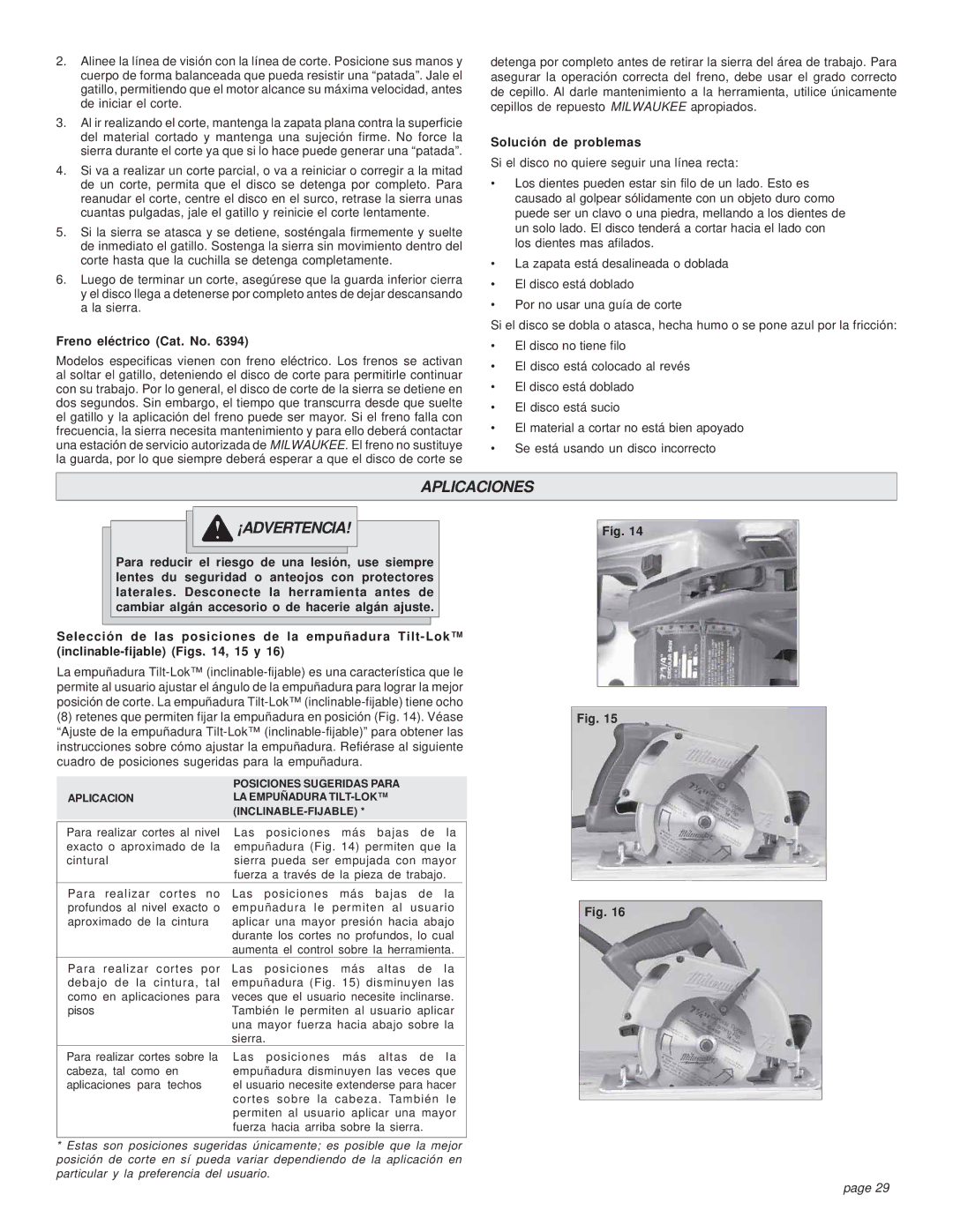
Milwaukee HEAVY-DUTY CIRCULAR SAW manual Tool Assembly, Selecting Blade, Adjusting Depth Figs

Page 6

TOOL ASSEMBLY

WARNING!

To reduce the risk of injury, always unplug tool before attaching or removing accessories or making adjustments. Use only specifically recommended accessories. Others may be hazardous.

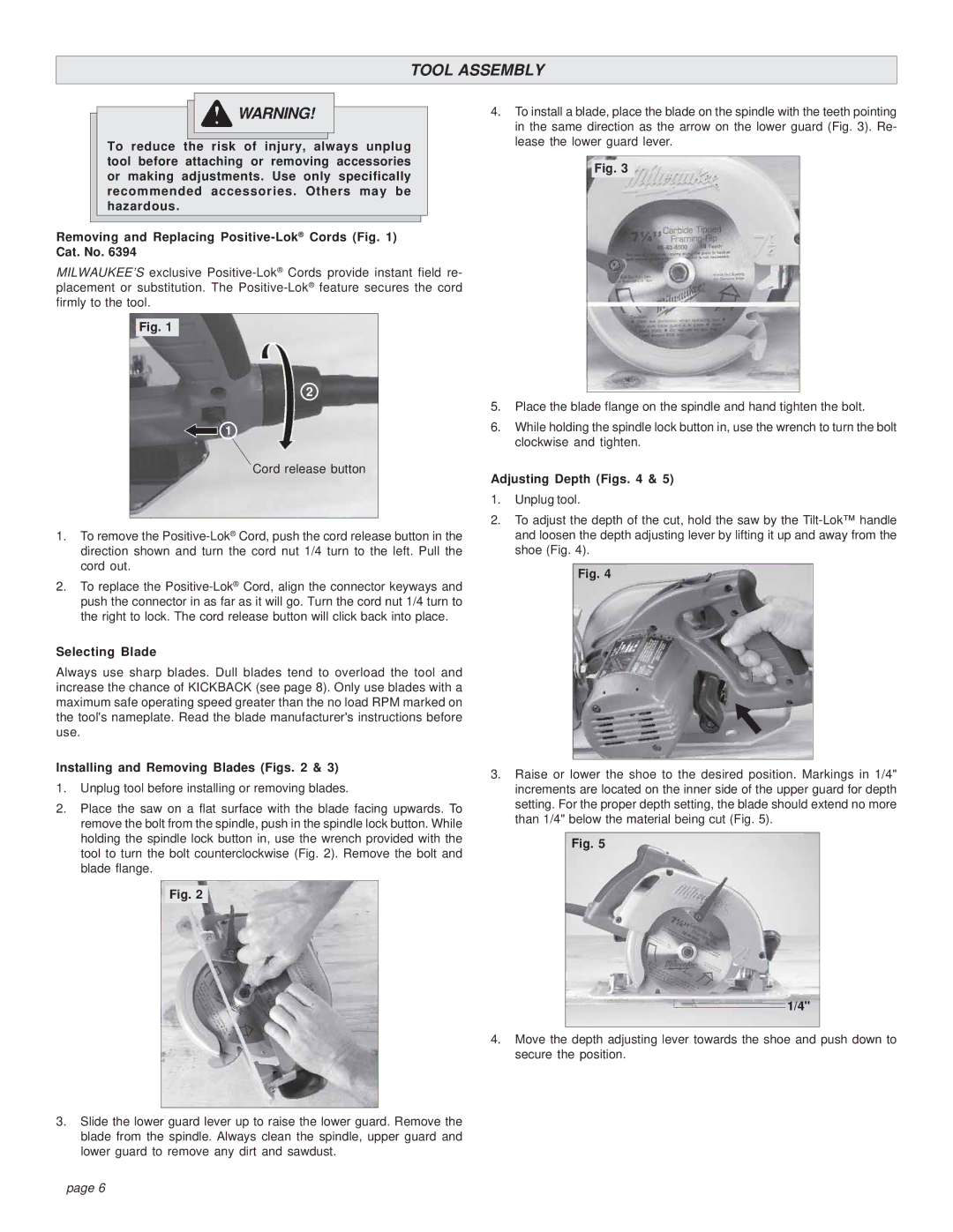
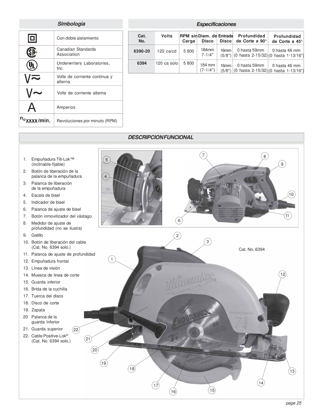
Removing and Replacing Positive-Lok®Cords (Fig. 1) Cat. No. 6394

MILWAUKEE’S exclusive Positive-Lok®Cords provide instant field re- placement or substitution. The Positive-Lok®feature secures the cord firmly to the tool.

Fig. 1

2

1

Cord release button

1.To remove the Positive-Lok®Cord, push the cord release button in the direction shown and turn the cord nut 1/4 turn to the left. Pull the cord out.

2.To replace the Positive-Lok®Cord, align the connector keyways and push the connector in as far as it will go. Turn the cord nut 1/4 turn to the right to lock. The cord release button will click back into place.

Selecting Blade

Always use sharp blades. Dull blades tend to overload the tool and increase the chance of KICKBACK (see page 8). Only use blades with a maximum safe operating speed greater than the no load RPM marked on the tool's nameplate. Read the blade manufacturer's instructions before use.

Installing and Removing Blades (Figs. 2 & 3)

1.Unplug tool before installing or removing blades.

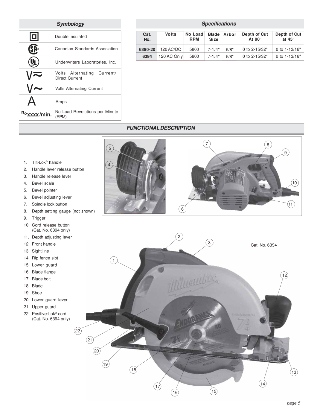
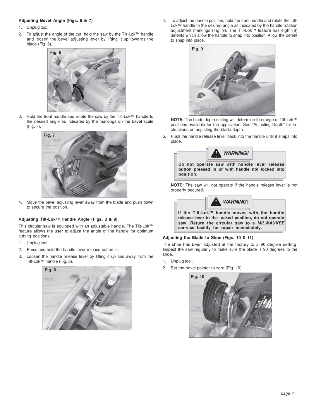
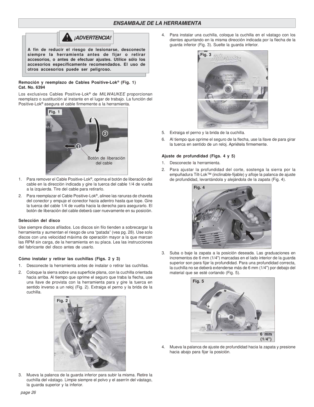
2.Place the saw on a flat surface with the blade facing upwards. To remove the bolt from the spindle, push in the spindle lock button. While holding the spindle lock button in, use the wrench provided with the tool to turn the bolt counterclockwise (Fig. 2). Remove the bolt and blade flange.

Fig. 2

3.Slide the lower guard lever up to raise the lower guard. Remove the blade from the spindle. Always clean the spindle, upper guard and lower guard to remove any dirt and sawdust.

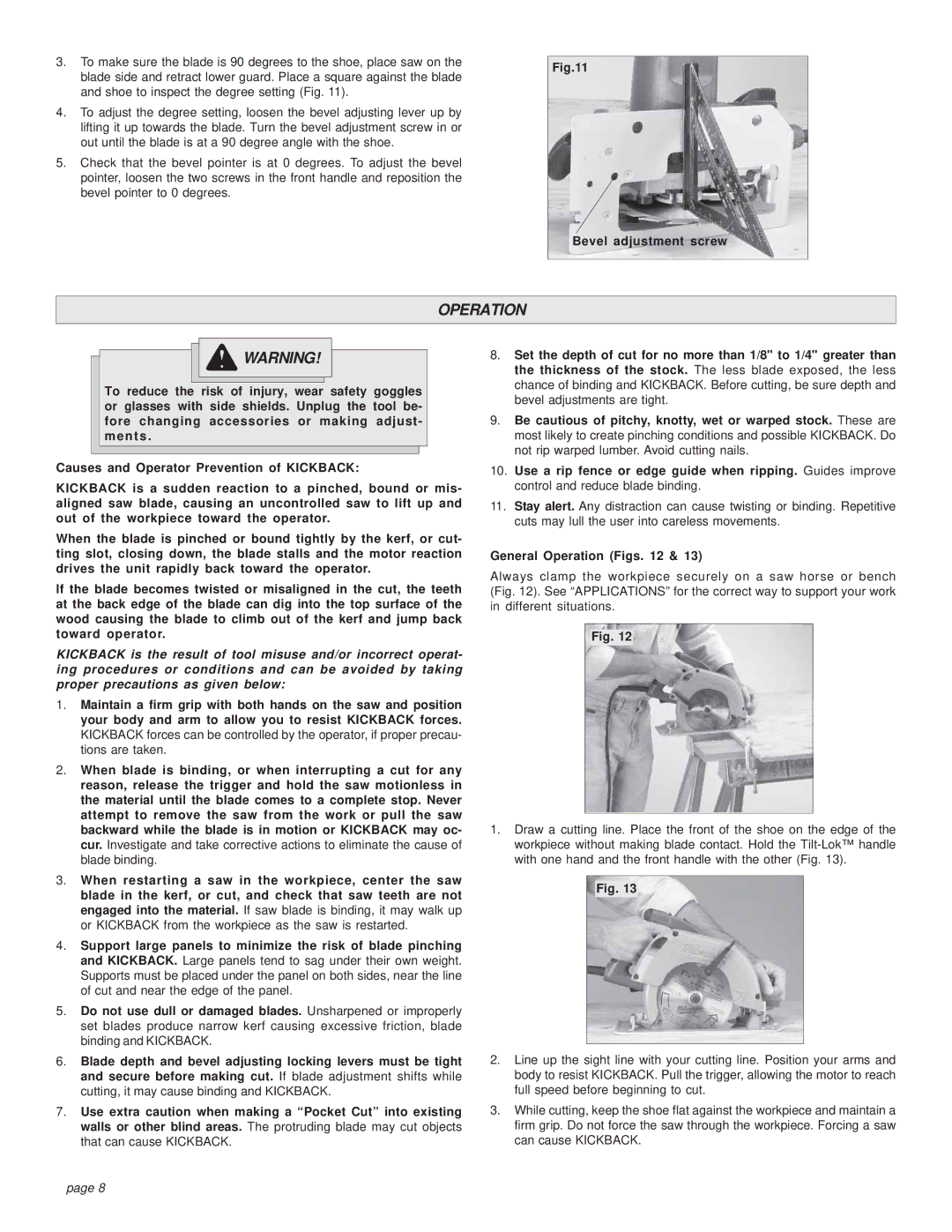
4.To install a blade, place the blade on the spindle with the teeth pointing in the same direction as the arrow on the lower guard (Fig. 3). Re- lease the lower guard lever.

Fig. 3

5.Place the blade flange on the spindle and hand tighten the bolt.

6.While holding the spindle lock button in, use the wrench to turn the bolt clockwise and tighten.

Adjusting Depth (Figs. 4 & 5)

1.Unplug tool.

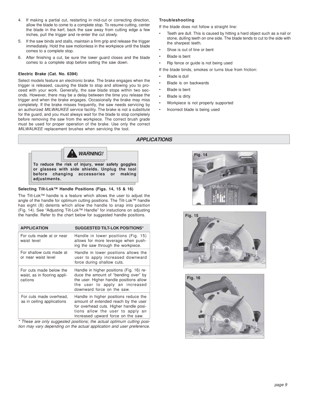
2.To adjust the depth of the cut, hold the saw by the Tilt-Lok™ handle and loosen the depth adjusting lever by lifting it up and away from the shoe (Fig. 4).

Fig. 4

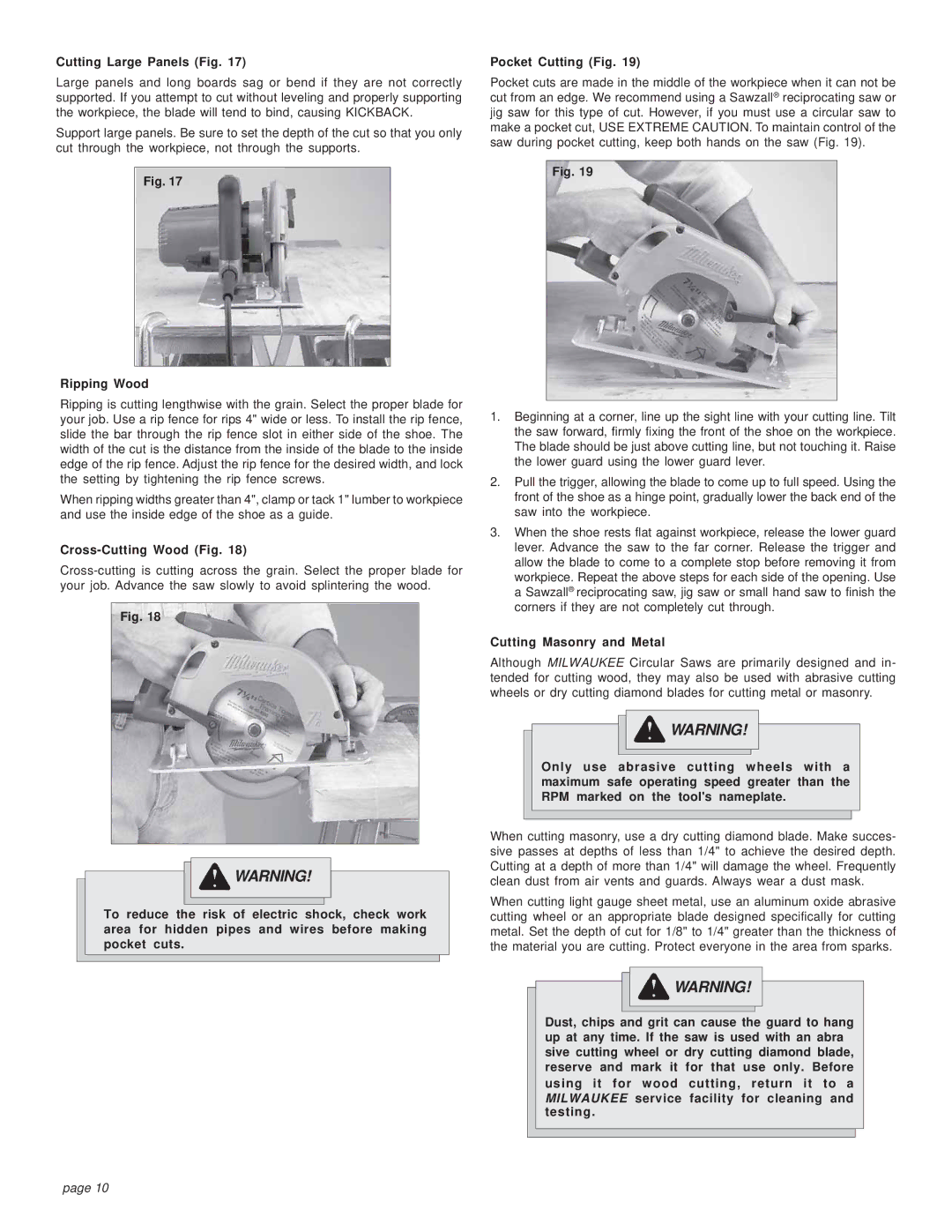
3.Raise or lower the shoe to the desired position. Markings in 1/4" increments are located on the inner side of the upper guard for depth setting. For the proper depth setting, the blade should extend no more than 1/4" below the material being cut (Fig. 5).

Fig. 5

1/4"

4. Move the depth adjusting lever towards the shoe and push down to secure the position.

page 6
Image 6
Contents Operators Manual Personal Safety Work Area Safety Power Tool USE and CareElectrical Safety ServiceSpecific Safety Rules Circular Saws Causes and Operator Prevention of KickbackGrounding Guidelines for Using Extension CordsRecommended Minimum Wire Gauge For Extension Cords Extension CordsSize 6390-20 FunctionaldescriptionCat Volts No Load Blade Arbor Depth of Cut 6394Adjusting Depth Figs Tool AssemblyInstalling and Removing Blades Figs Selecting BladeAdjusting Bevel Angle Figs Adjusting Tilt-Lok Handle Angle FigsBevel adjustment screw OperationGeneral Operation Figs Troubleshooting ApplicationsElectric Brake Cat. No Cross-Cutting Wood Fig Cutting Large Panels FigRipping Wood Cutting Masonry and MetalAccessories MaintenanceFive Year Tool Limited Warranty RepairsSécurité Individuelle Conserver CES Instructions Sécurité DU Lieu DE TravailSécurité Électrique UTILISATIONETENTRETIENDEL’OUTILÉLECTRIQUERègles DE Sécurité Particulière Scies Circulaire Causes du retour d’outil et prévention par l’utilisateurCordons DE Rallonge Calibres minimaux recommandés pour Les cordons de rallongeMise À LA Terre Avertissement Outils pourvus d’une fiche de cordon à deux dentsPictographie Spécifications DescriptionfonctionnelleChoix des lames Installation et retrait de la lame Figs etMontage DE Loutil Avertissement Réglage de profondeur Figs etVis de réglage de biseau Figs et Réglage de l’angle de la poignée Tilt-Lok Figs etManiement Avertissement Vis du biseauRègles générales d’opération Figs et Frein Életronique No de cat Dépistage des dérangementsCoupe transversale du bois Fig Coupe des grands panneaux FigRefente du bois Coupe dans la maçonnerie ou les métauxGarantie Limitée DE L’OUTIL DE Cinq ANS Maintenance AvertissementAccessoires Avertissement RéparationsSeguridad Personal GUA0RDE Estas Instrucciones Seguridad EN EL Área DE TrabajoSeguridad Eléctrica USO Y Cuidado DE LAS Herramientas EléctricasReglas Especificas DE Seguridad Sierras Circulares Tierra ¡ADVERTENCIA Extensiónes EléctricasGuías para el uso de cables de extensión Descripcionfuncional Cat Volts RPM sin Diam. deProfundidad Carga Disco De Corte a 6390-20 Cómo instalar y retirar las cuchillas Figs y Ensambaje DE LA Herramienta ¡ADVERTENCIASelección del disco Ajuste de profundidad Figs yCómo ajustar el ángulo del bisel Figs y Operacion ¡ADVERTENCIA Tornillo de ajuste de biselOperación en general Figs y Solución de problemas AplicacionesFreno eléctrico Cat. No Cortando madera a través Fig Cortando paneles grandes FigCortando a lo largo Corte de concreto y metalAccesorios ¡ADVERTENCIA Mantenimiento ¡ADVERTENCIAGarantía Limitada DE Cinco Años ReparacionesSawdust