Carrier 52S manual Cleaning the Indoor and Outdoor Coils, Coils section, Section Components on

Page 14

52S

SERIES

CLEANING THE INDOOR AND OUTDOOR COILS

Coil ®ns are sharp and may cut hands. Wear heavy protective gloves when cleaning coils.

1.Use a vacuum cleaner or soft bristle brush to remove surface ®bers and dirt from each of the faces of the coil. Both the inner and outer surfaces of the coils must be cleaned. It is important to apply the tool in the same direction of the ®ns, not against them. Applying the tool against the ®ns may cause damage (®n edges may bend over).

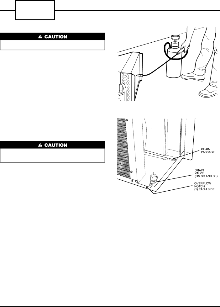
2.With a tank sprayer or a trigger spray extension tube, spray coil cleaning solution evenly across the coils, making sure coils are thoroughly saturated. See Figure 28. Refer to instructions on the cleaning solu- tion containers for best results. Do not use a high pressure sprayer.

3.Rinse the coils thoroughly with low-velocity, clean water.

4.Repeat steps 2 and 3.

5.Drain water and cleaning solution that may have collected in the basepan during the cleaning pro- cess by carefully tilting the chassis. This allows excess water to ¯ow out of the over¯ow notches.

Do not set unit on end to drain water from basepan, or at any other time. Oil will drain from the compres- sor sump, which could cause compressor failure.

6.Thoroughly clean the basepan and drain passages by rinsing with clean water. Be sure all debris is re- moved from the drain valve. See Figure 29.

7.Allow unit components to air dry before reassem- bling the unit. Once dry, reassemble by reversing Steps 1 - 9 from the Accessing Indoor and Outdoor

Coils section.

ACCESSING THE INDOOR FAN AND INDOOR

FAN SCROLL Ð Dried debris and build-up on the blower wheel and blower scroll can reduce the ef®ciency of the unit. To properly access the indoor fan and in- door fan scroll for cleaning, refer to the GENERAL DISASSEMBLY section under To Access Indoor-Air

Section Components on page 6.

FIGURE 28 Ð CLEANING THE COILS

FIGURE 29 Ð BASEPAN SECTION

14

Image 14
Contents Service Technician Guide ContentsIntroduction Summary of DANGERS, WARNINGS, and CautionsModel Number Nomenclature To Open the Control BOX General DisassemblyTo Disconnect Power for CORD- Connected Unit To Remove the Unit from the Wall SleeveDuct Extension Screws To Access INDOOR-AIR Section Components Removing the AIR BaffleTo Remove the AIR Discharge Grille To Remove the TOP Cover Ð Remove the screwTo Remove the Gusset To Access OUTDOOR-AIR Section ComponentsTo Remove the Discharge Deck Removing Stator Component Cleaning Schedule General CleaningCleaning and Safety Consider the following safety issues before beginning Replacing the Indoor AIR Filter Ð Access Monthly Cleaning Cleaning the Indoor AIR Filter Ð Remove Tools NeededChassis Cleaning the Vent AIR FilterReplacing the Vent AIR Filter Disconnect ALL Power to Unit Seasonal CleaningAccessing the Indoor and Outdoor Coils section Cleaning the Indoor and Outdoor CoilsAccessing the Indoor FAN and Indoor Section Components onCleaning the Heater Assembly Ð Once Cleaning the Indoor FAN and FANDisconnect ALL Power to the Unit Compressor Rotary Compressor ComponentsCompressor Troubleshooting Basic Hermetic Compressor Electrical MeasurementsBasic Compressor Troubleshooting Guide Compressor Replacement SHORTED/OPEN Windings TestDisconnect all power to unit Removing the Compressor Ð Follow the stepsInstalled Filter Drier Refrigerant Charging Ð Every mechanicalHeater Removal HeatersCommon Causes Heater Failure Removing Heater Screws Operating Controls Typical 52S Unit Operating ControlsHigh Heat or High Cool Ð Push button Description of Switch SettingsNON-USER Adjustable Switches Outside or Vent AIR Ð Push the FAN onlyCooling only Units Figure Sequence of OperationHEAT/COOL Units Figure Heat Pump Units FigureIndoor Thermostat Heat Pump Units Component Operation and TroubleshootingTools Needed Indoor Thermostat IT CONTACTS, ALL 52SQ AA and CP Models Outdoor Frost Thermostat Heat Pump UnitsLocked OUT Capacitor TestElectrical Components Removal and Replacement Outdoor Frost Thermostat ScrewsComponent Locations Open Control BOX Basic FAN Motor Electrical Tests FAN Motor TroubleshootingFAN Motor FAN Motor Troubleshooting Chart Typical 208/230 Volt Motors Typical 265 Volt MotorsFAN Motor Replacement RemovalField Temperature Charts 52S Series Page 52S Series Page 52S Series Page 52S Series Page 52S Series Page 52S Series Page 52S Series Page 52S Series Wiring Schematics Wiring Schematic 52SC Ð 208/230 V and 265 V AA and CP UnitsWiring Schematic 52SE Ð 208/230 V and 265 V AA and CP Units Wiring Schematic 52SE Ð 208/230 V and 265 V RC Units Wiring Schematic 52SQ Ð 208/230 V and 265 V AA and CP Units Wiring Schematic 52SQ Ð 208/230 V and 265 V RC Units Most Frequent Ptac Service Questions