Grizzly G1021 instruction manual Power Feed, Handwheel, Depth Limiter

Page 30

Power Feed

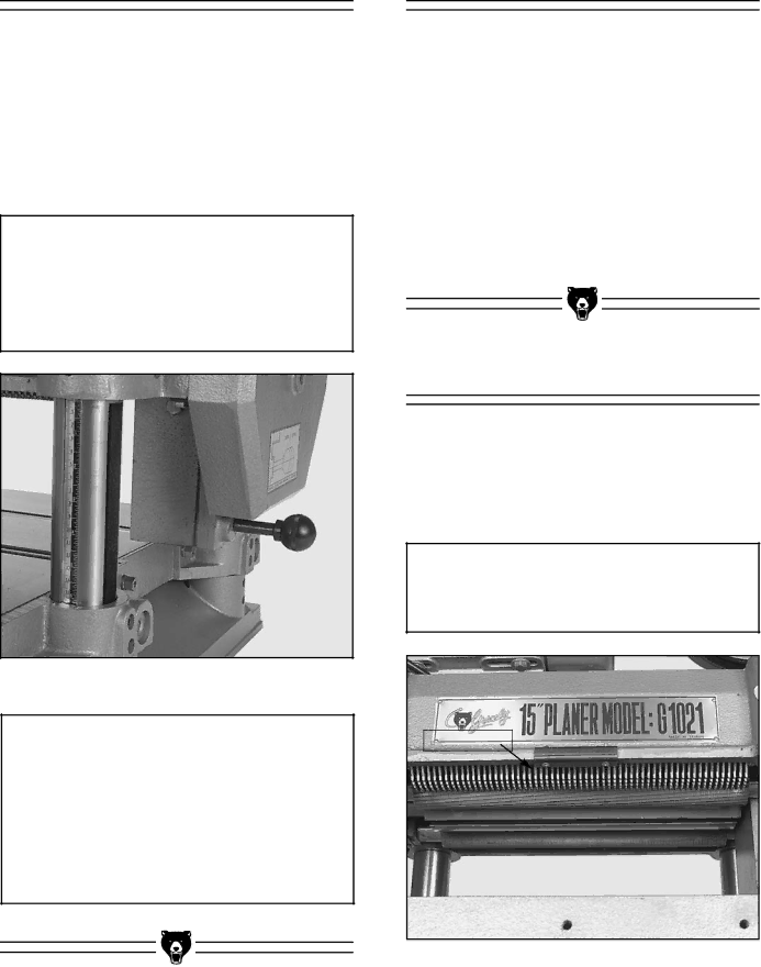
The power feed features two feed rates; 16 FPM and 20 FPM. When running the machine, the operator can control the feed speed by moving the feed control knob. Moving the knob toward the machine produces the 20 FPM feed speed, away from the machine produces 16 FPM and a center position places the gear box in neutral.

Figure 35.

CAUTION

The feed rate should be set while the planer is running but before feeding lumber into it. DO NOT attempt to change speeds after the cutting operation has begun.

Figure 35. Feed speed adjustment knob.

CAUTION

If you take a cut that is too large, the planer will bog down noticeably. The motor may even stall. If this happens, turn off the power immediately, lower the table, and remove your workpiece. Re-adjust your table to allow a lesser cut and repeat your operation.

-30-

Handwheel

Crank the handwheel to raise or lower the table according to the desired workpiece thickness.

Each complete revolution of the handwheel moves the table by 5/32" (4mm). Make sure the height scale is properly adjusted.

With the limiting clip installed, you cannot cut more than 1/8" in a single pass. While cutting this much material is possible, it is not recommended. Take it slow and easy. The quality of your work will be better and your planer will last longer.

Depth Limiter

The Model G1021 is equipped with a depth lim- iter – located on the bottom of the cutterhead casting just under the nameplate. See Figure 36. The depth limiter controls maximum depth of cut to 1/8".

CAUTION

To avoid mechanical damage to the planer, do not remove the depth limiter.

Depth Limiter

Figure 36. Location of depth limiter.

G1021 15" Planer

Image 30
Contents Planer Page Table Of Contents Adjustment Block Pattern Warranty and Returns Safety Safety Instructions For Power ToolsSafety Instructions For Power Tools Additional Safety Instructions For Planers 220V Operation Grounding FusingCircuit Requirements Extension CordsIntroduction CommentaryUnpacking Parts InventoryClean Up Site ConsiderationsAssembly OverviewOptional Stand Starter Switch Planer UnitTo Mount the Planer Handwheel Knife Setting Jig To Assemble the Knife Setting JIGTo Mount the Handwheel Extension Rollers Dust Port To Attach the Extension RollersTo Attach the Dust Port Adjustments Overview of planer adjustment controls G1021 15 PlanerTable Adjustment Gauge BlockTo Check Table Parallelism Knife Inspection To Inspect the KnivesKnife Setting To SET the KnivesTo Adjust the Chipbreaker Chip BreakerFeed Roller Height To Check Roller HeightTo Adjust Roller Height To Adjust Roller PressureFeed Roller Pressure To Adjust the BED Rollers Bed RollersTo Adjust the Chip Deflector Chip DeflectorTo INSPECT/ADJUST the Pulleys Anti-KickbackBeltsGearbox To Check Belt TensionTo Inspect the Gearbox Extension Rollers Extension RollersTo Adjust the Scale Thickness ScaleOperations Table LocksPower Feed HandwheelDepth Limiter Test Run Wood Species Type Shear PSIPlaning Difficulties Maintenance GeneralKnivesLubrication Fill DrainAdjustment Section Closure Troubleshooting Symptom Possible Cause Corrective ActionReference 145 79 80 146 See page 41-42 for Reference Number Listing See page 41-42 for Reference Number Listing Pulley Cover PK06M G1021 15 Planer Warranty and Returns