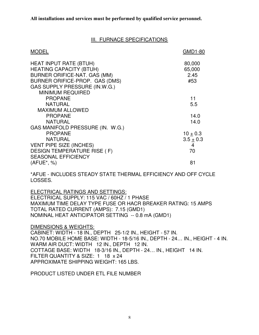

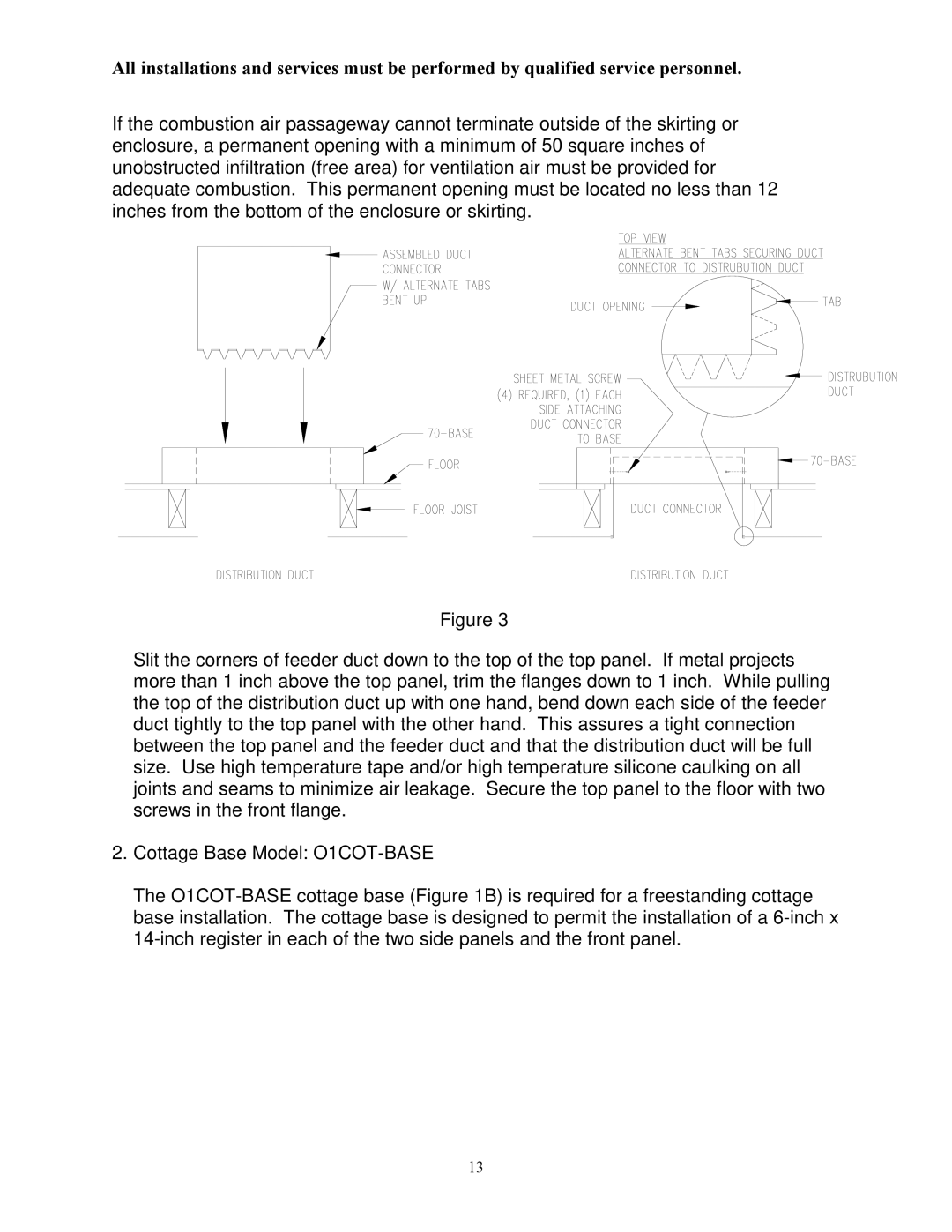
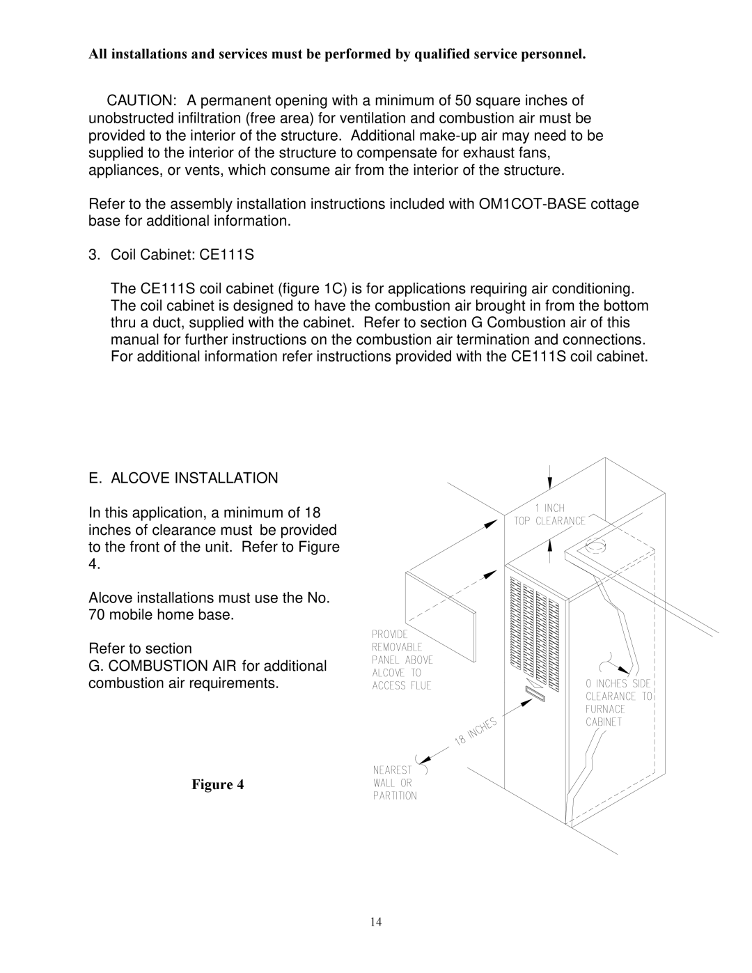
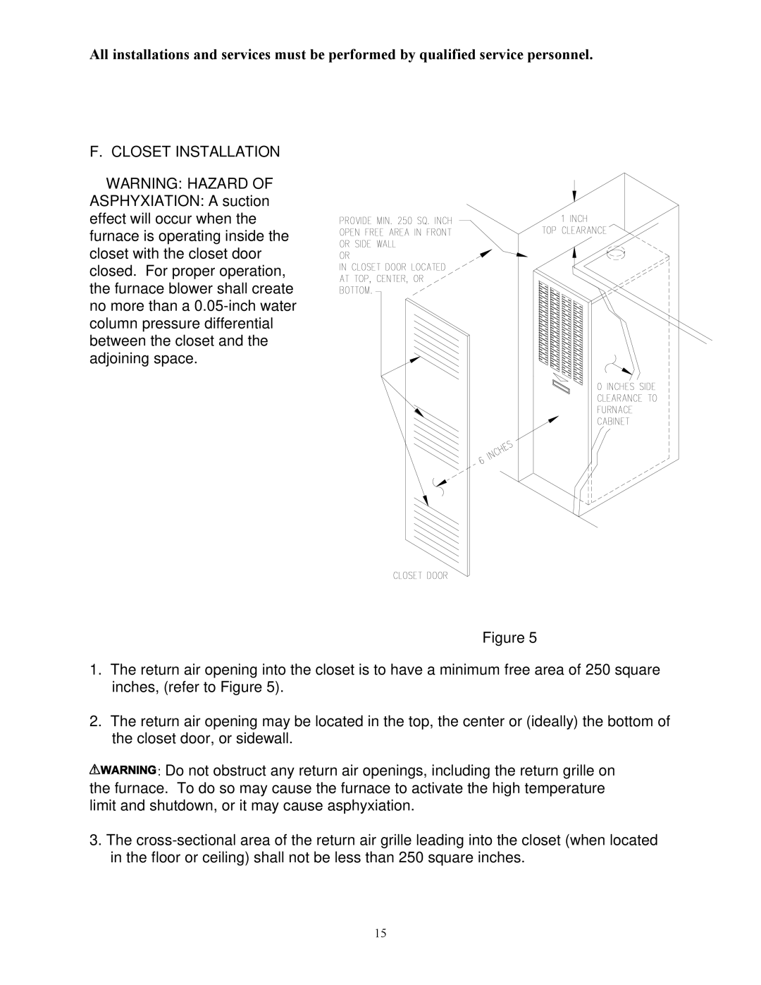
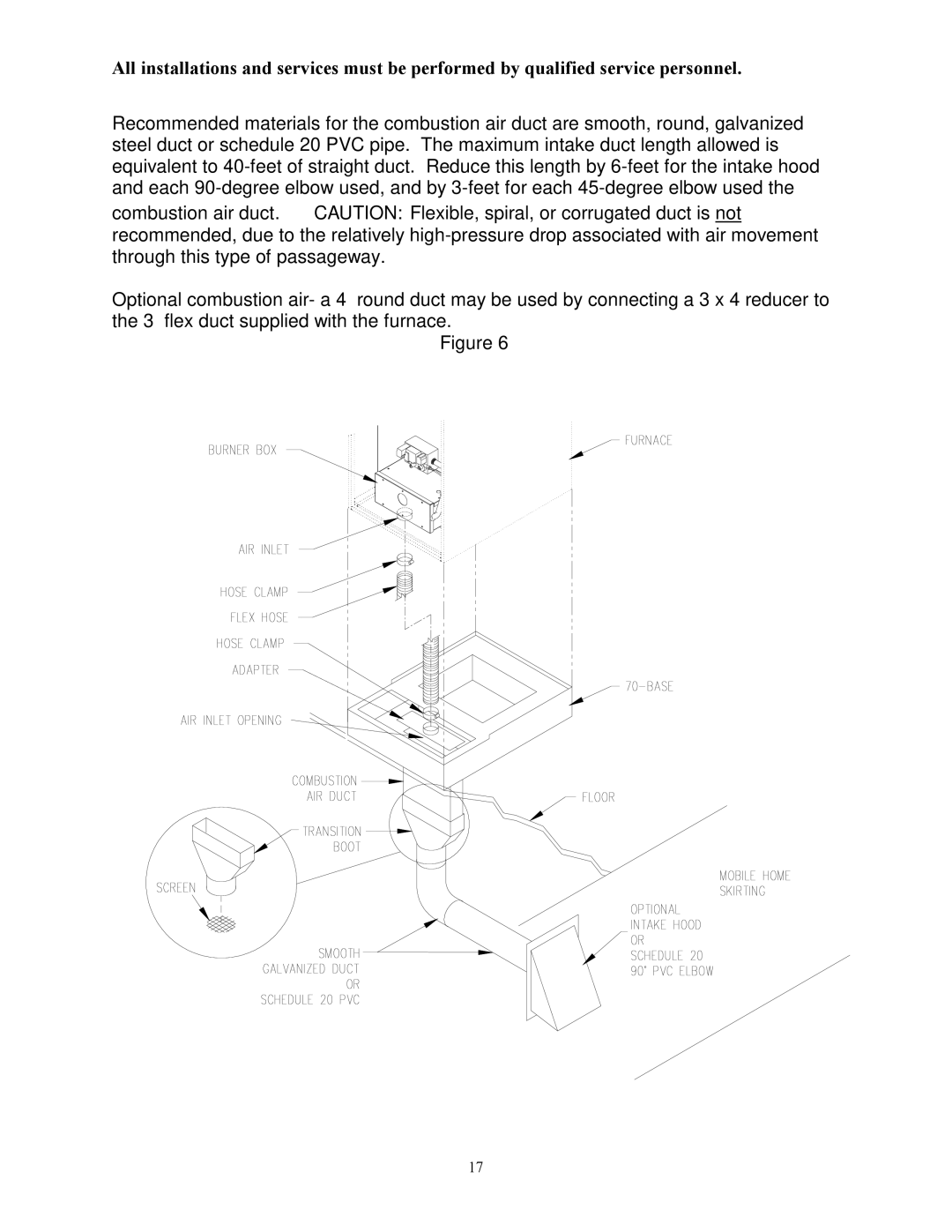
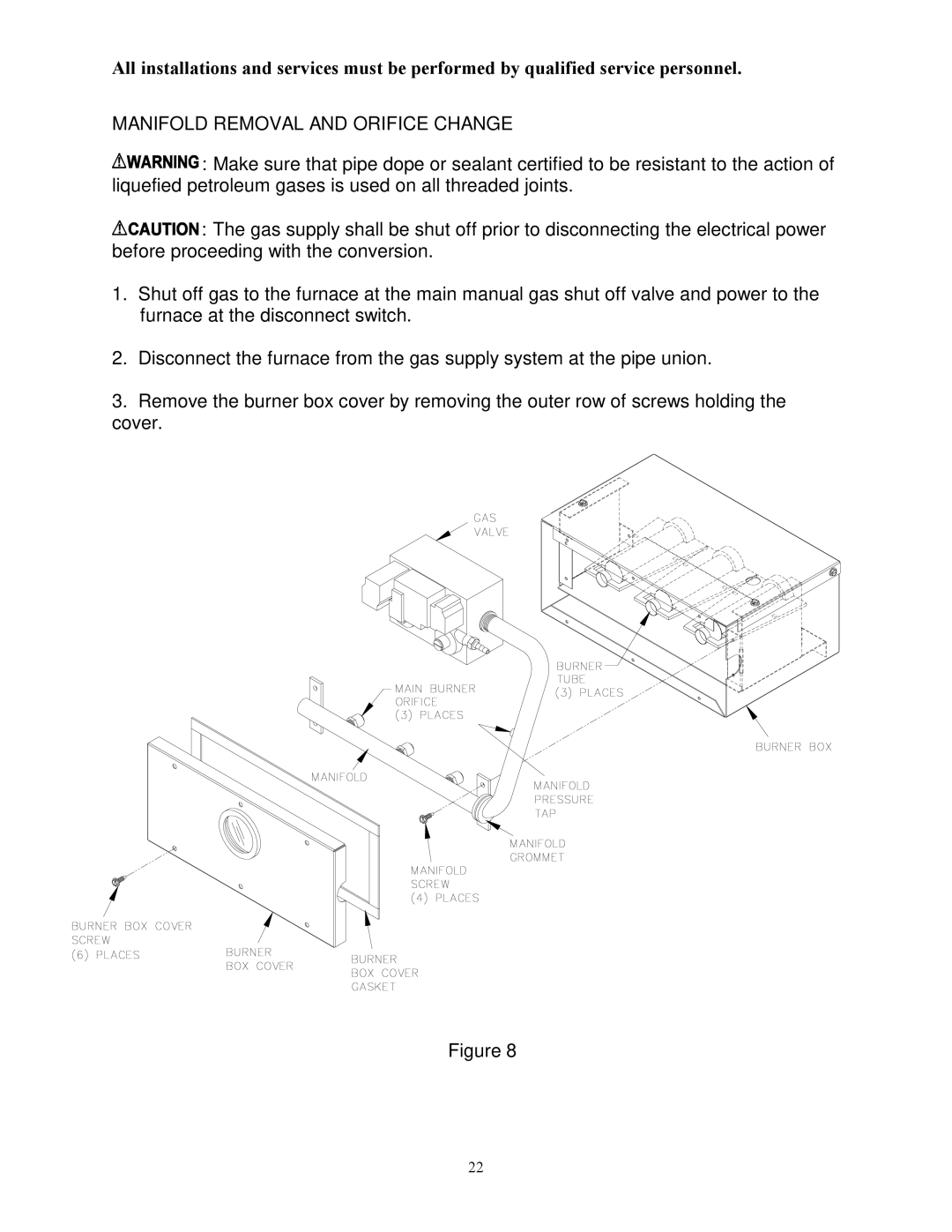
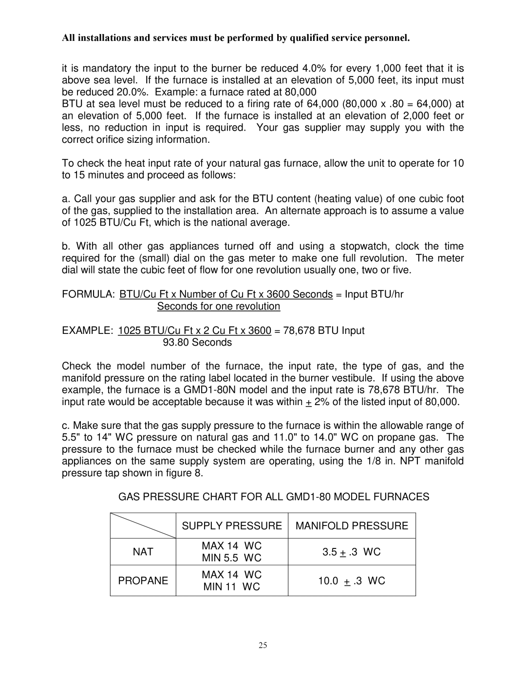

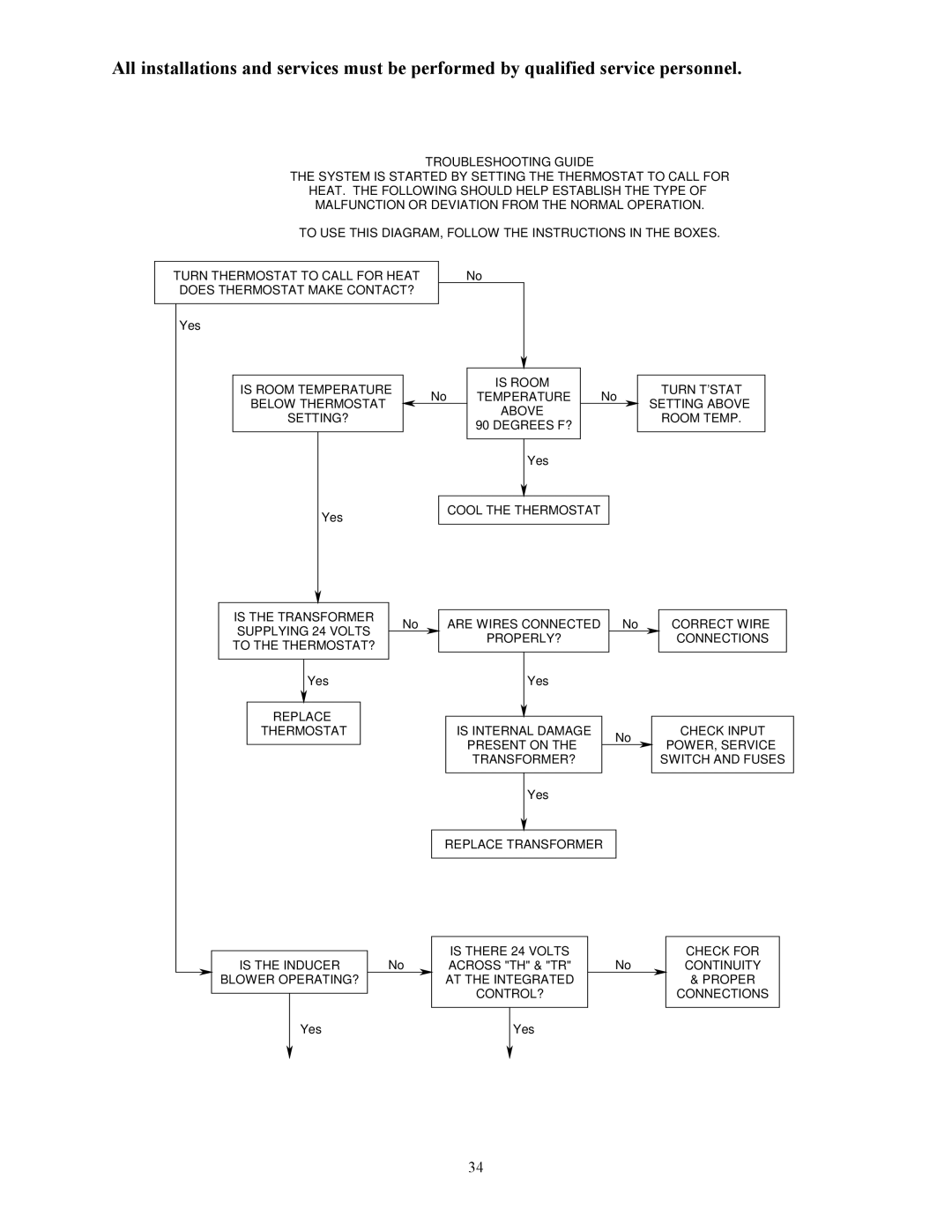
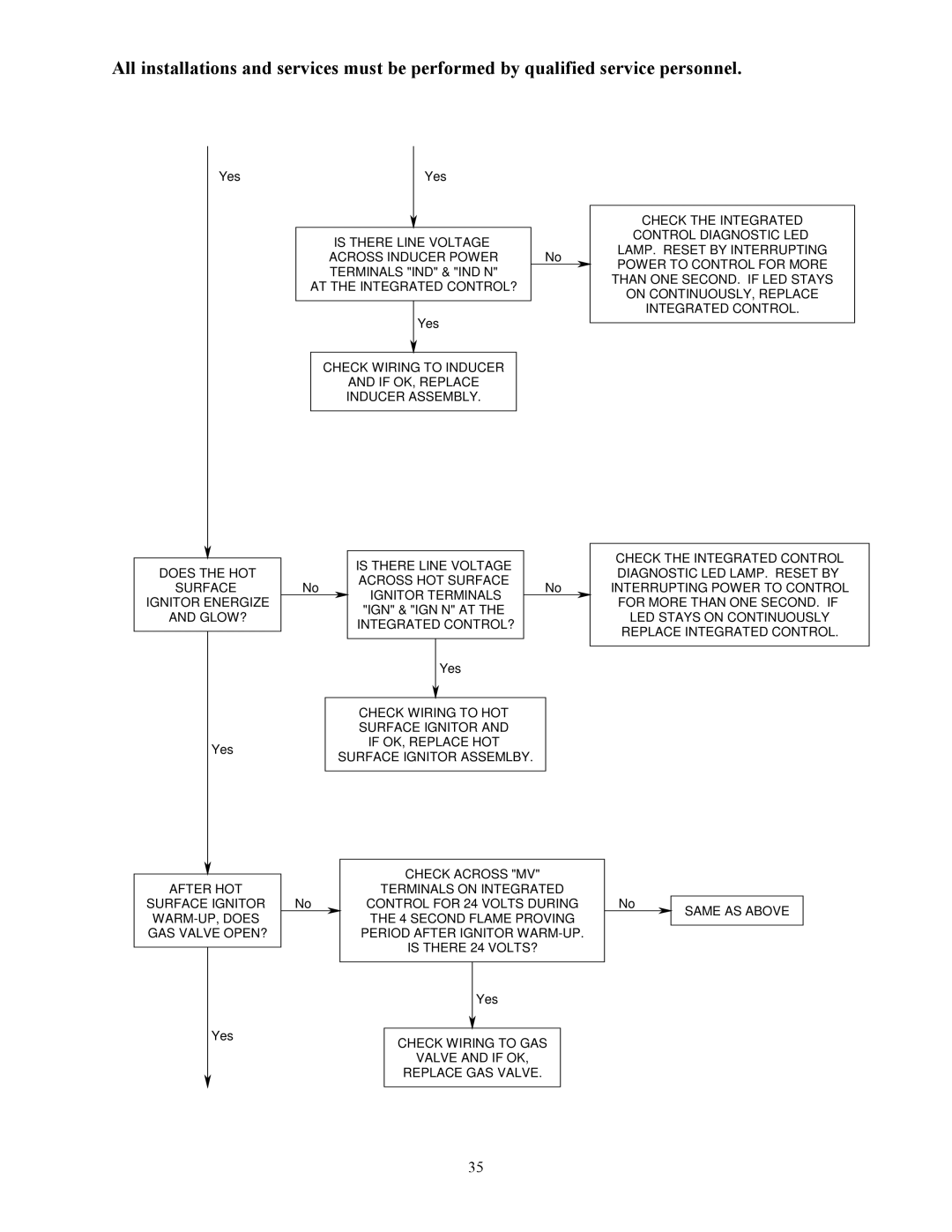
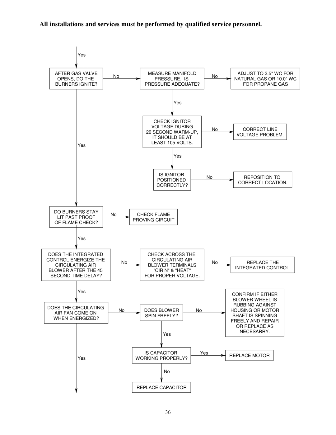
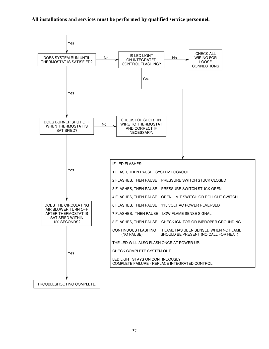
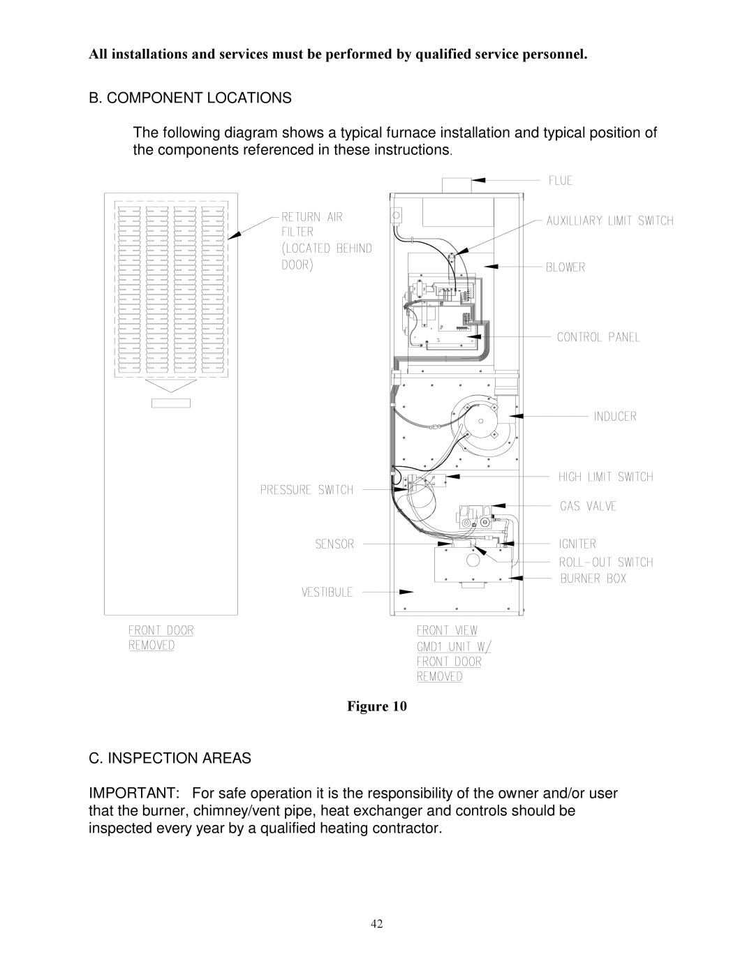
All installations and services must be performed by qualified service personnel.
f.Reinstall and secure the junction box cover with the original mounting screws.
3.Connection Of Room Thermostat Wires
NOTE: Class 1 thermostat wire must be used inside the furnace burner compartment.
a.Insert 24 VAC wires through the plastic grommet on the left side of the furnace casing.
b.Connect the thermostat wires to the W/R
c.Connect the thermostat wires to the room thermostat.
IMPORTANT: The room thermostat should be installed 4 to 5 feet above the floor on an interior wall which is relatively free from direct sources of heat (sunlight or supply airflow) or exposure to cold (drafts from open windows and doors). The nominal anticipator setting is 0.8 amperes, for the GMD (refer to the thermostat literature for additional information).
Electrical Wire Diameter
(AWG)
24
22
20
18
Maximum Recommended
Thermostat Wire Length
(Feet)
55
90
140
225
Once the furnace is installed, check the thermostat anticipator for proper nominal setting.
1.Connect a multimeter, capable of reading milliamps (mA), in series with the low voltage wires to the thermostat.
1.Increase the thermostat setting, or create a “call for heat”.
2.Read the value of the thermostat current, in milliamps.
3.Adjust the heat anticipator of the thermostat to the value read by the multimeter.
If the heat anticipator is set too high, the furnace may delay activation of a heating cycle for too long. If the heat anticipator is set too low, the furnace may cycle too frequently. Either condition may not provide optimal comfort to the homeowner.
20