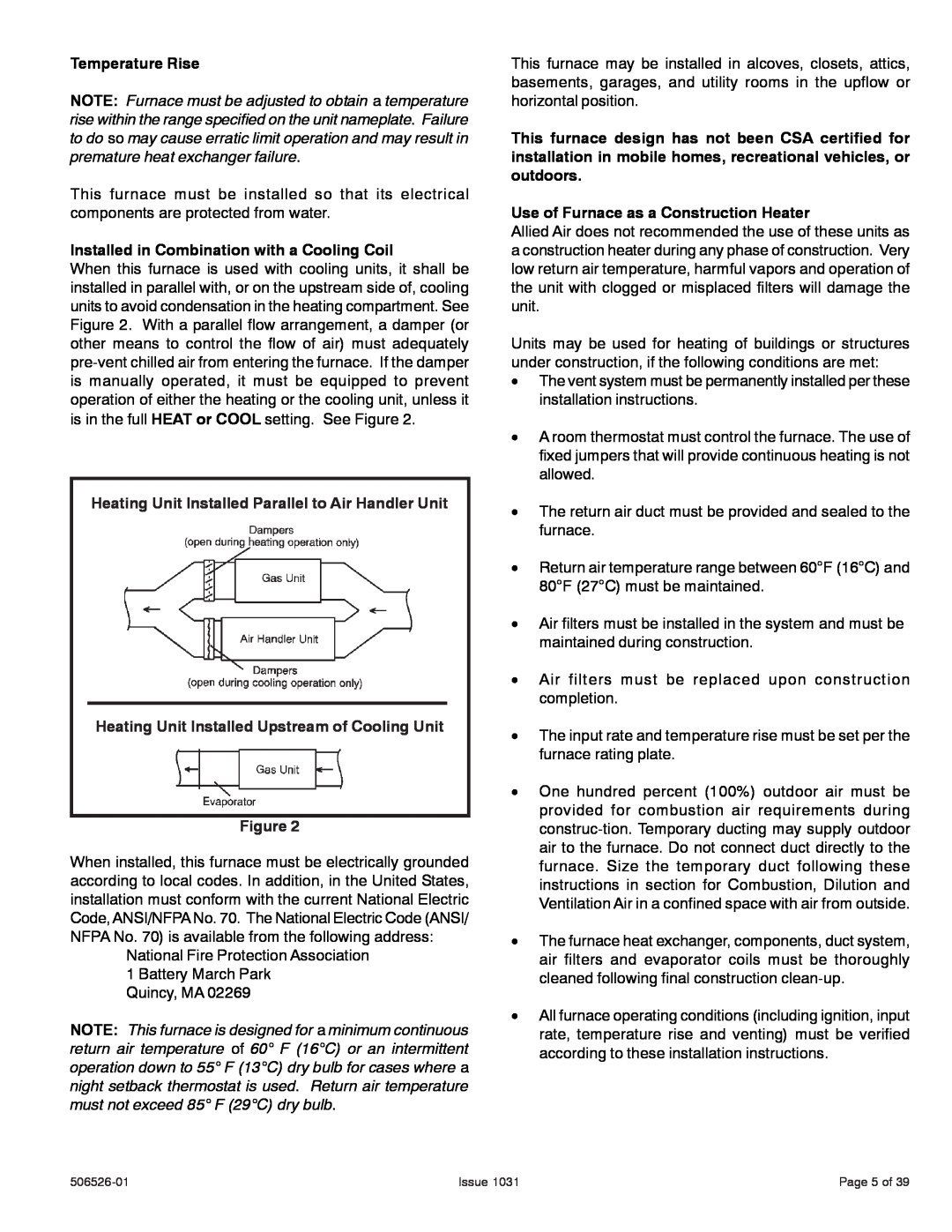
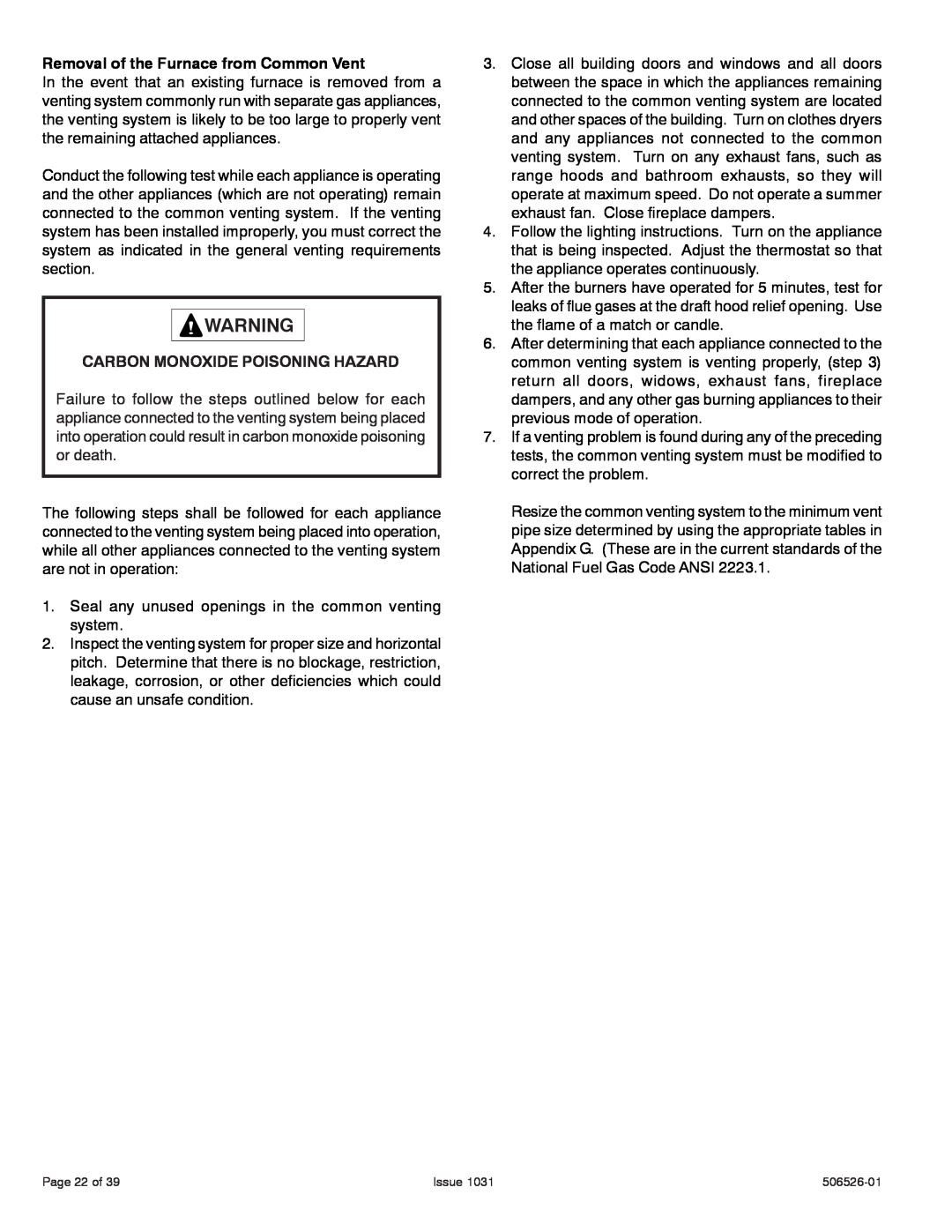
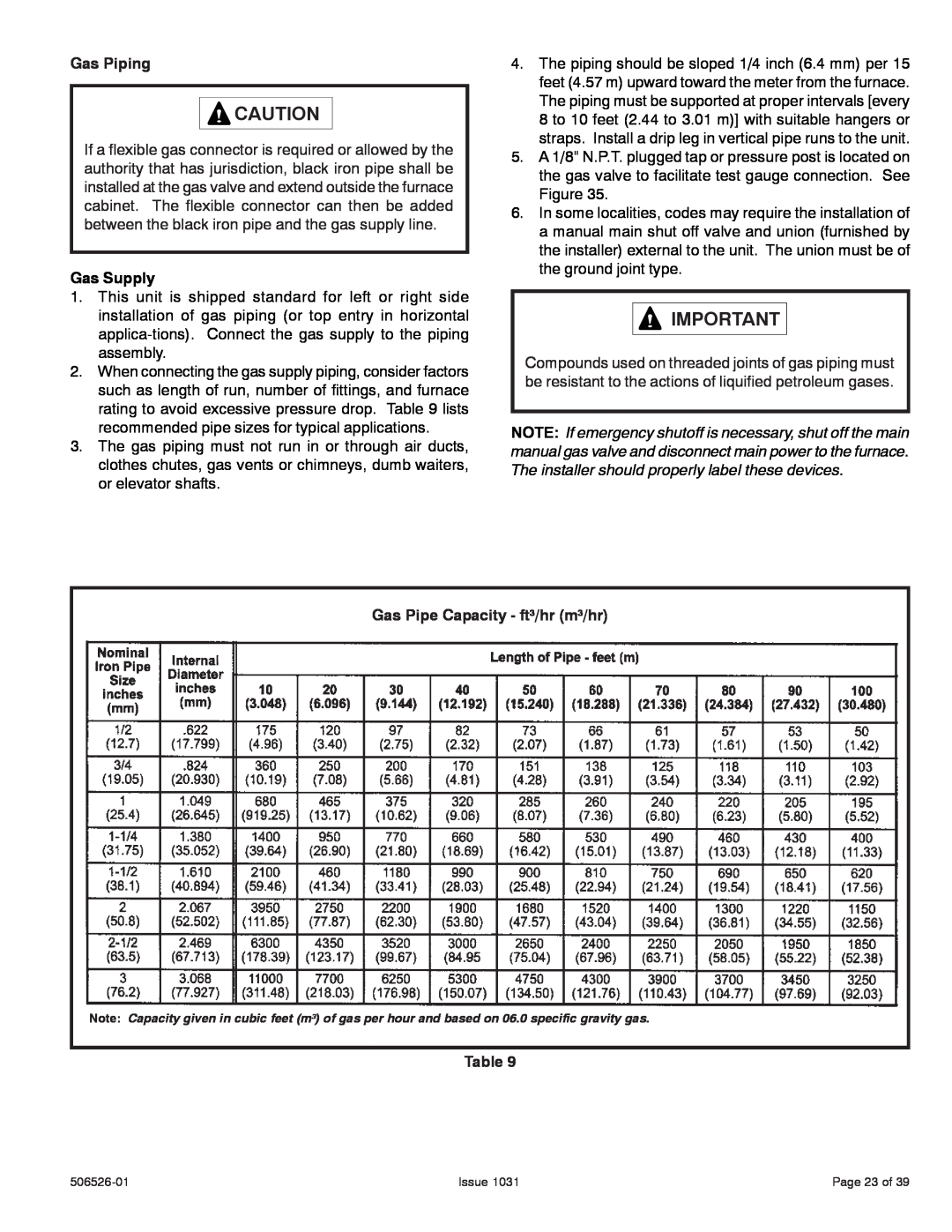
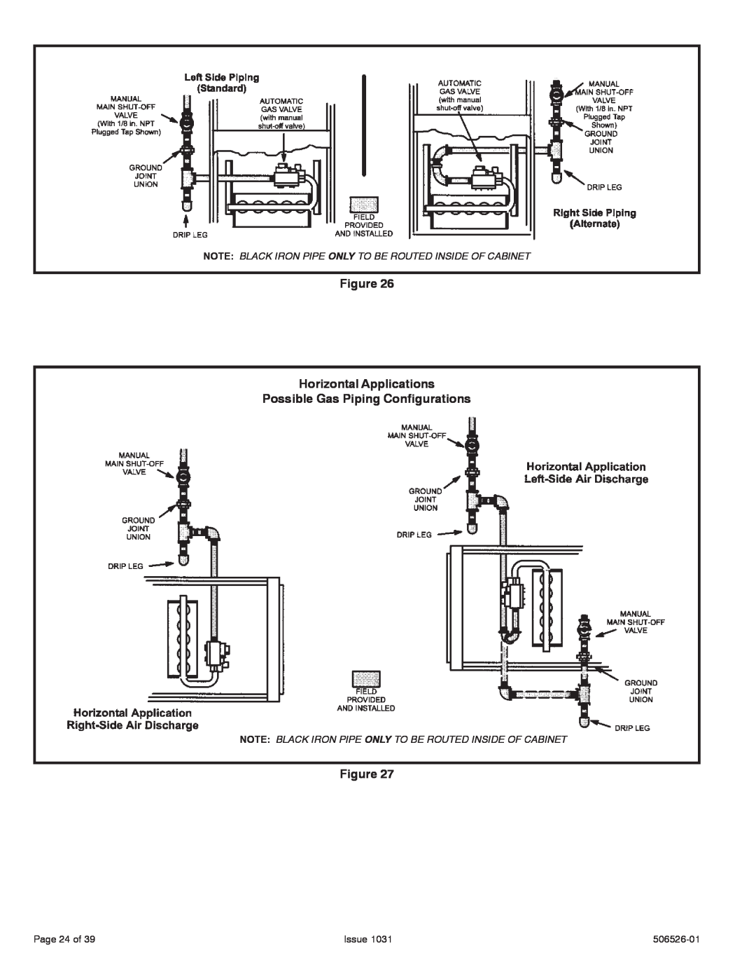
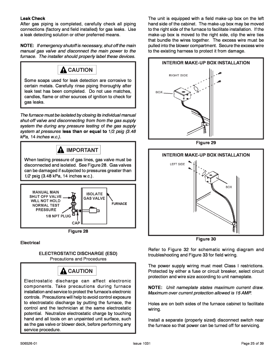
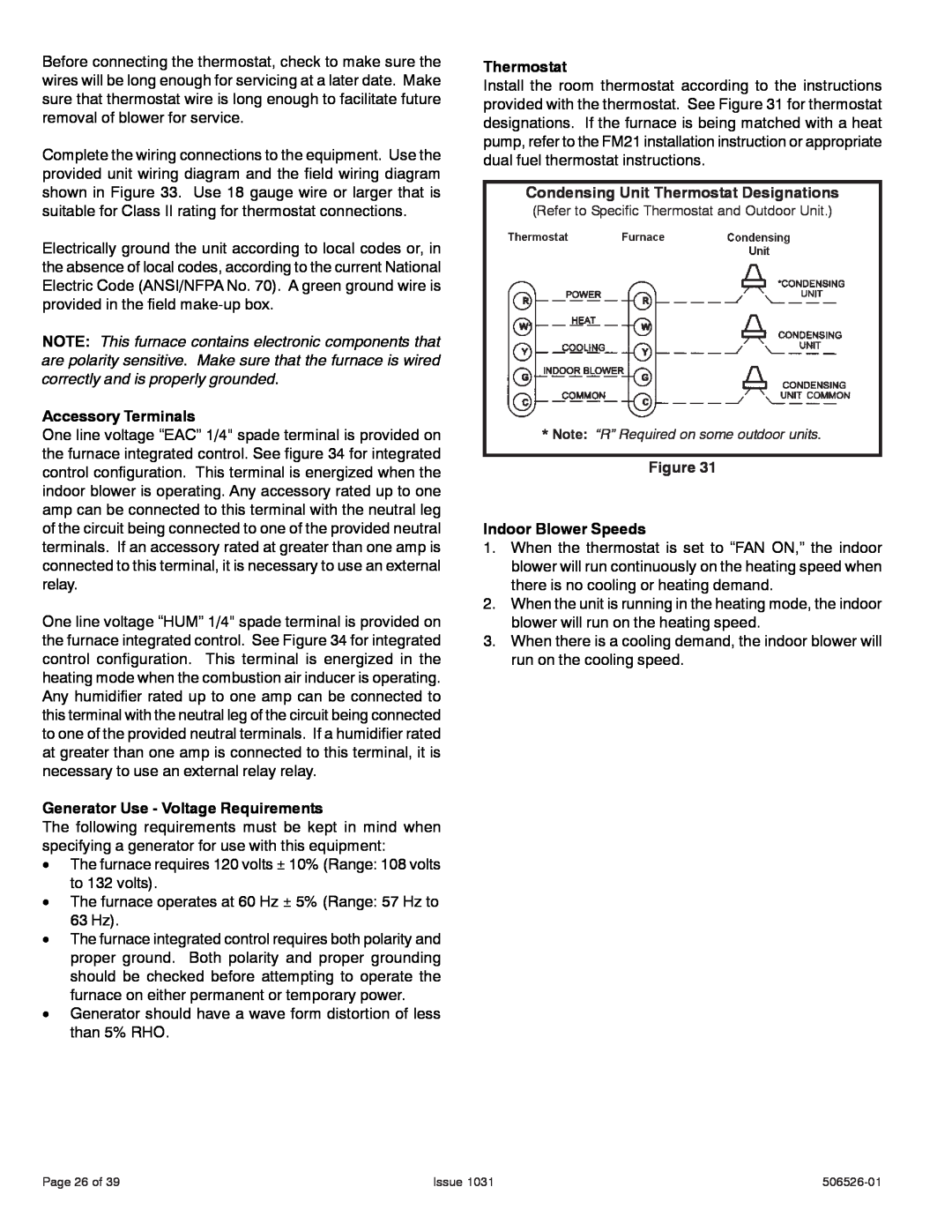
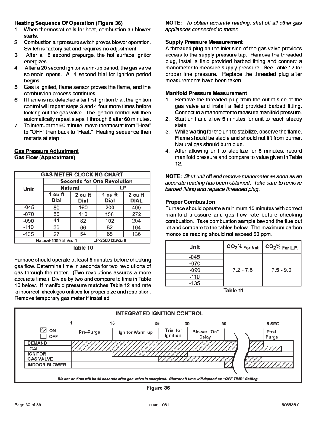
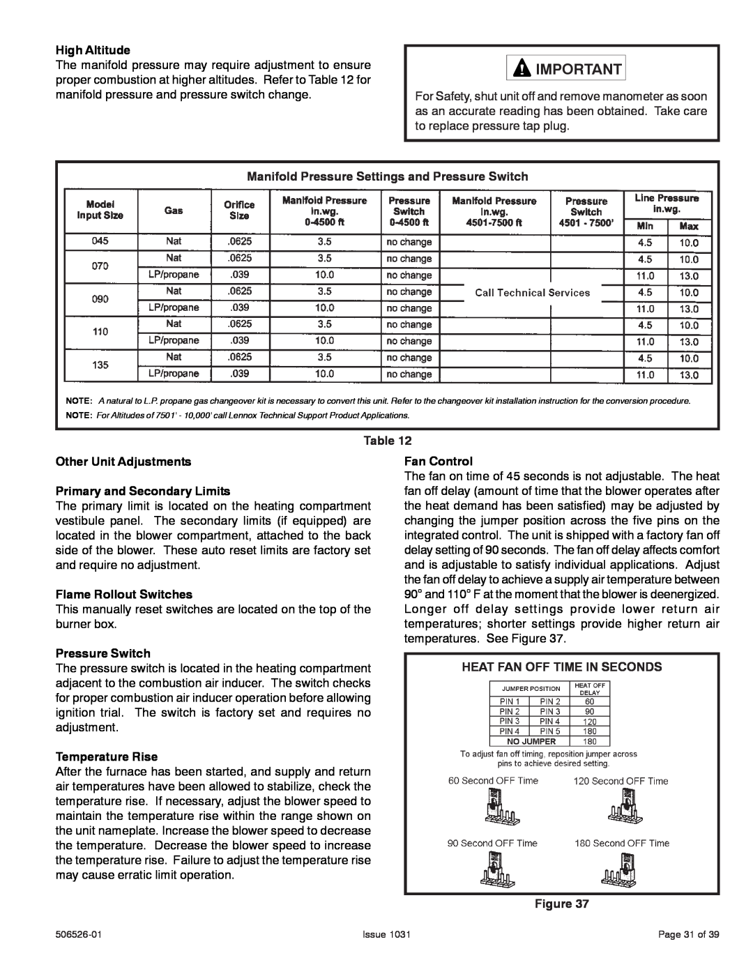
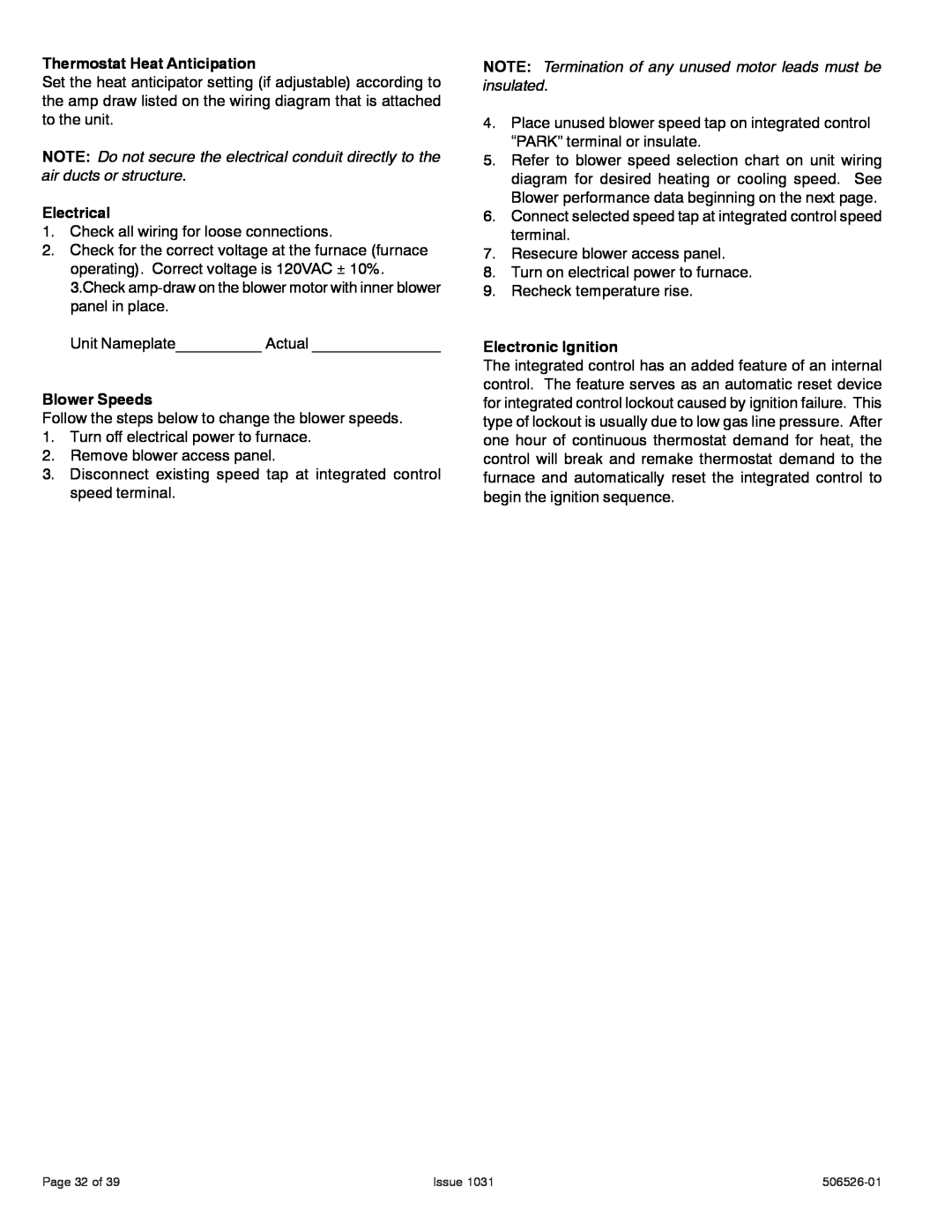
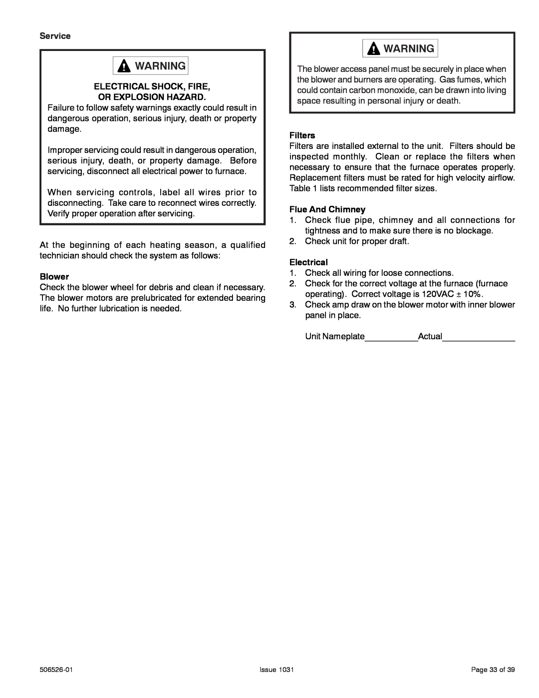
Allied Air Enterprises 80G1UH Removing the Bottom Panel Figure, Horizontal Applications

Page 11
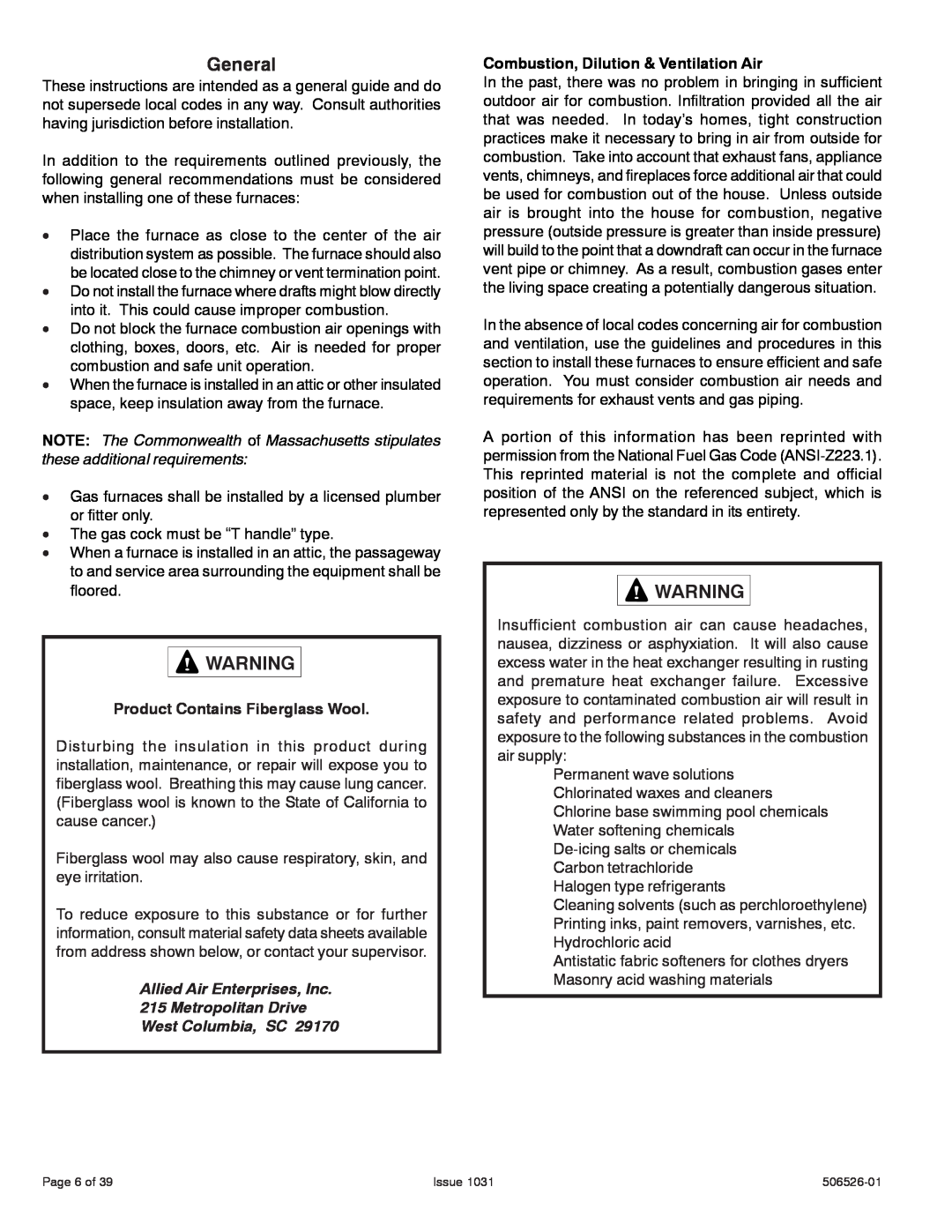
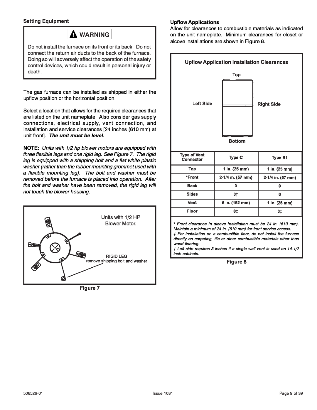
Removing the Bottom Panel

Removing the Bottom Panel

Remove the two screws that secure the bottom cap to the furnace. Pivot the bottom cap down to release the bottom panel. Once the bottom panel has been removed, reinstall the bottom cap. See Figure 11.

Removing the Bottom Panel

Figure 11

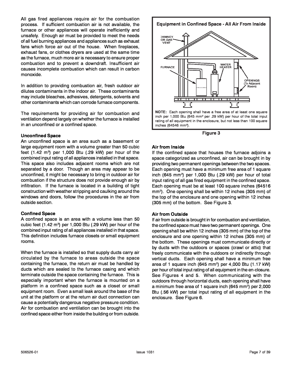
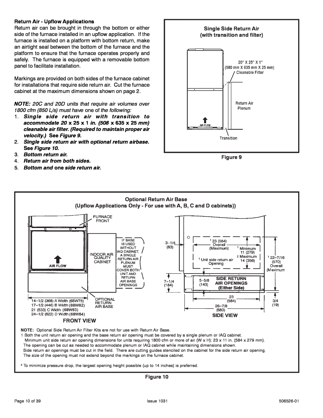
Horizontal Application

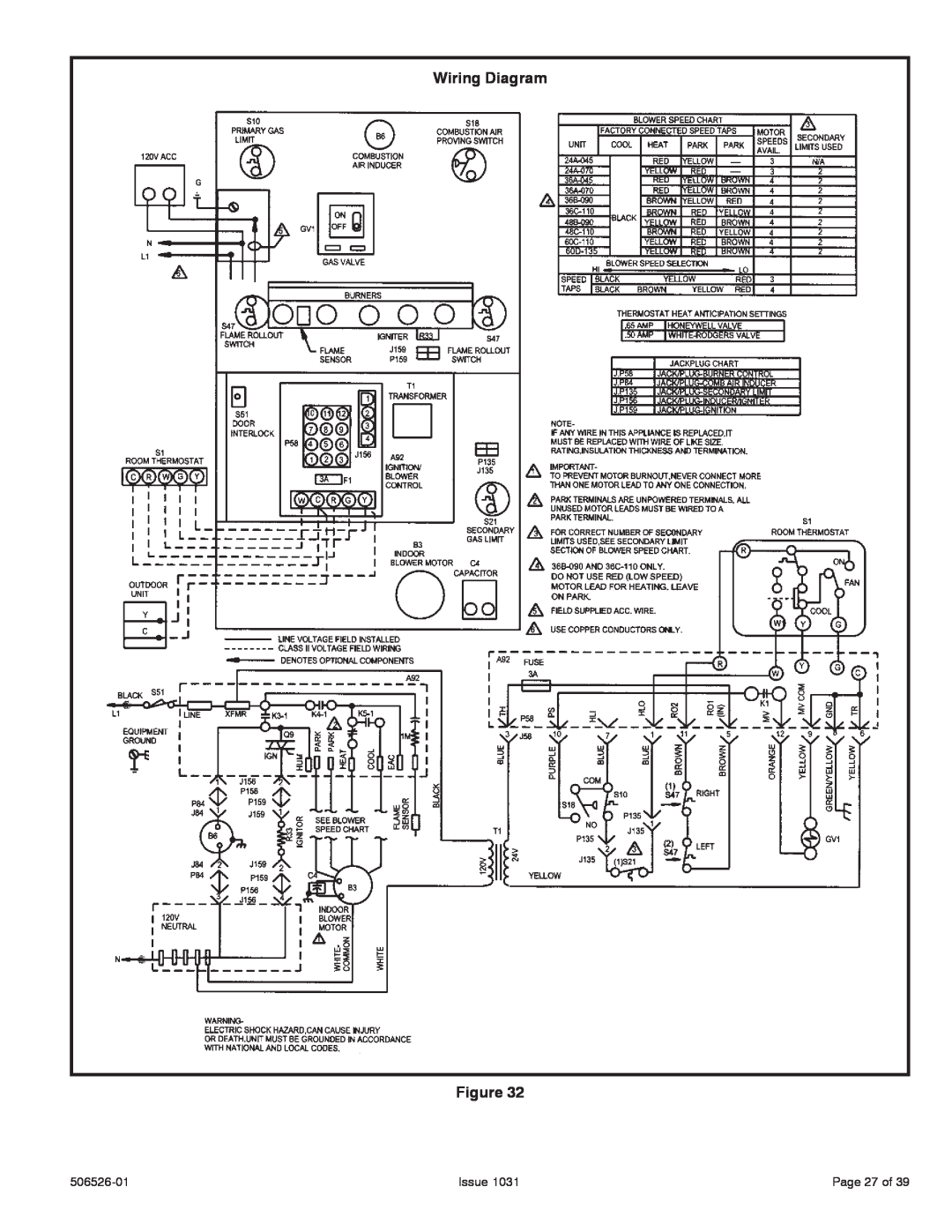
Installatioin clearances

*Front clearance in alcove installation must be 24 in. (610 mm). Maintain a minimum of 21 in. (610 mm) for front service access.

‡ For installations on a combustible floor, do not install the furnace directly on carpeting, tile or other combustible materials other than wood flooring.

Figure 12

Horizontal Applications

The furnace can be installed in horizontal applications. Order horizontal suspension kit (51W10) from Allied Air, or use equivalent suspension method.

Allow for clearances to combustible materials as indicated on the unit nameplate. Minimum clearances for closet or alcove installations are shown in Figure 12.

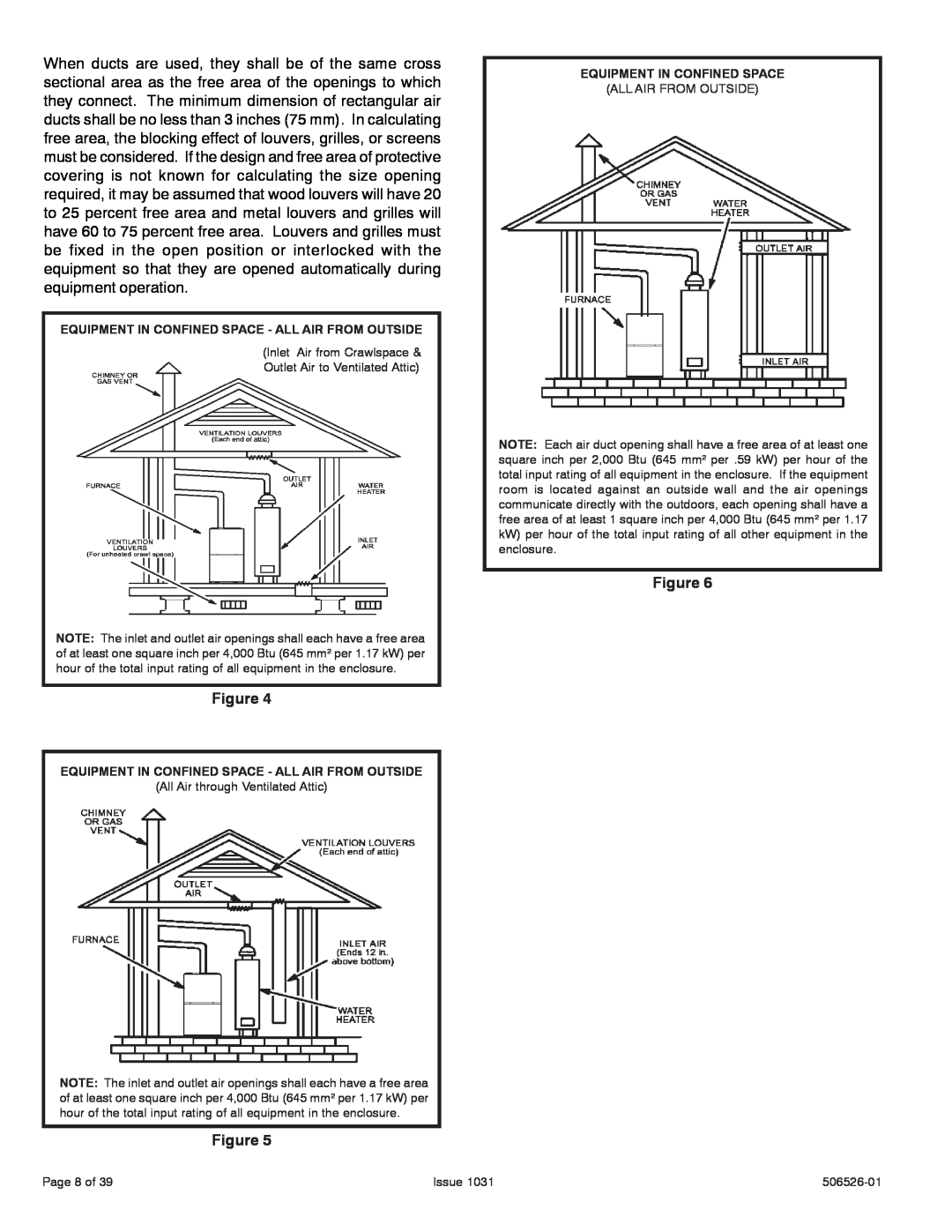
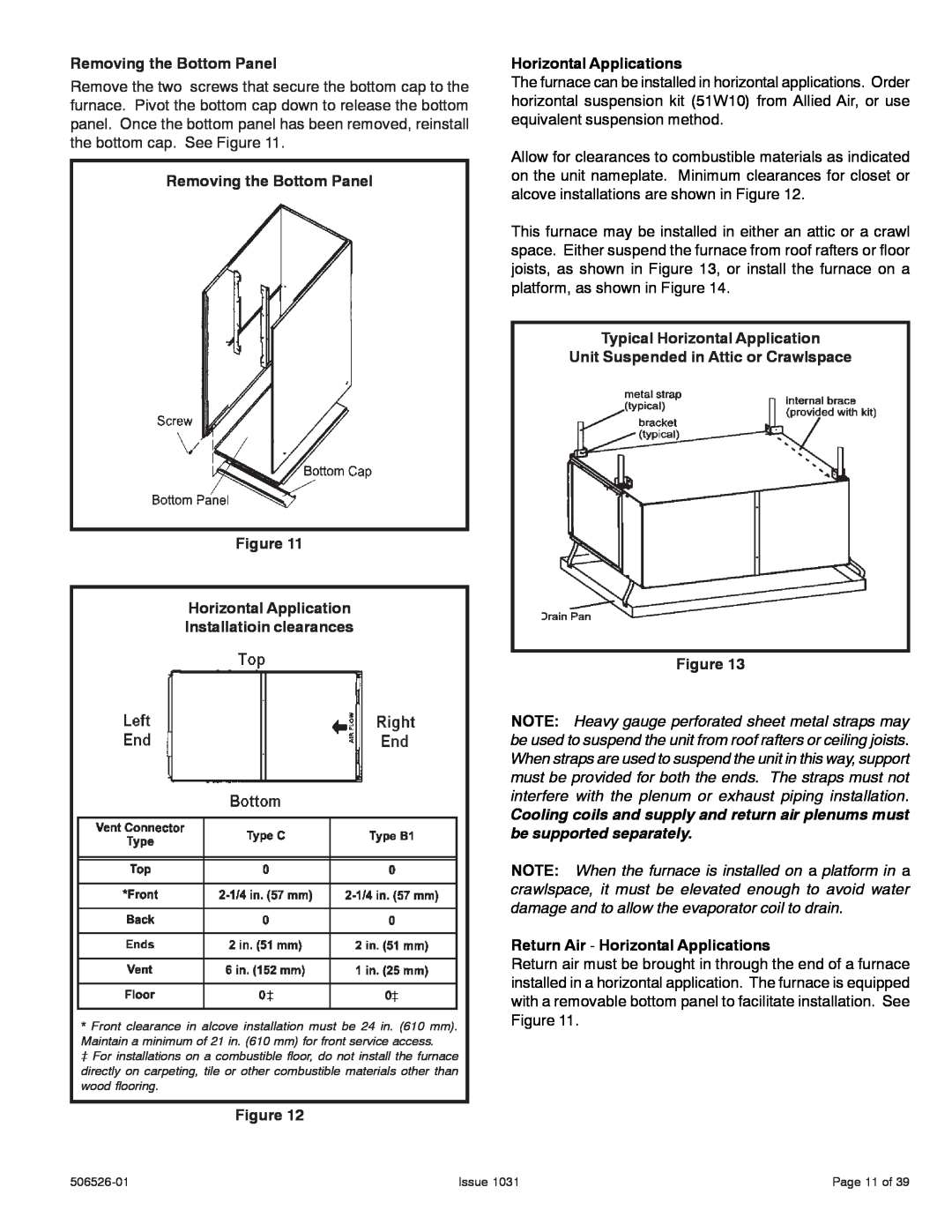
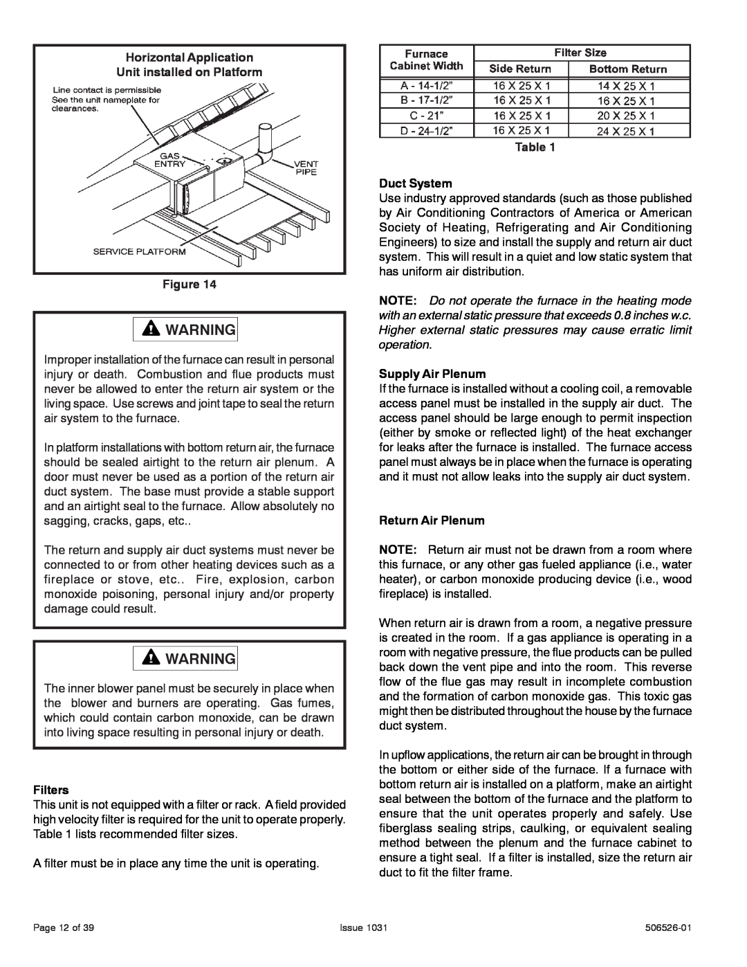
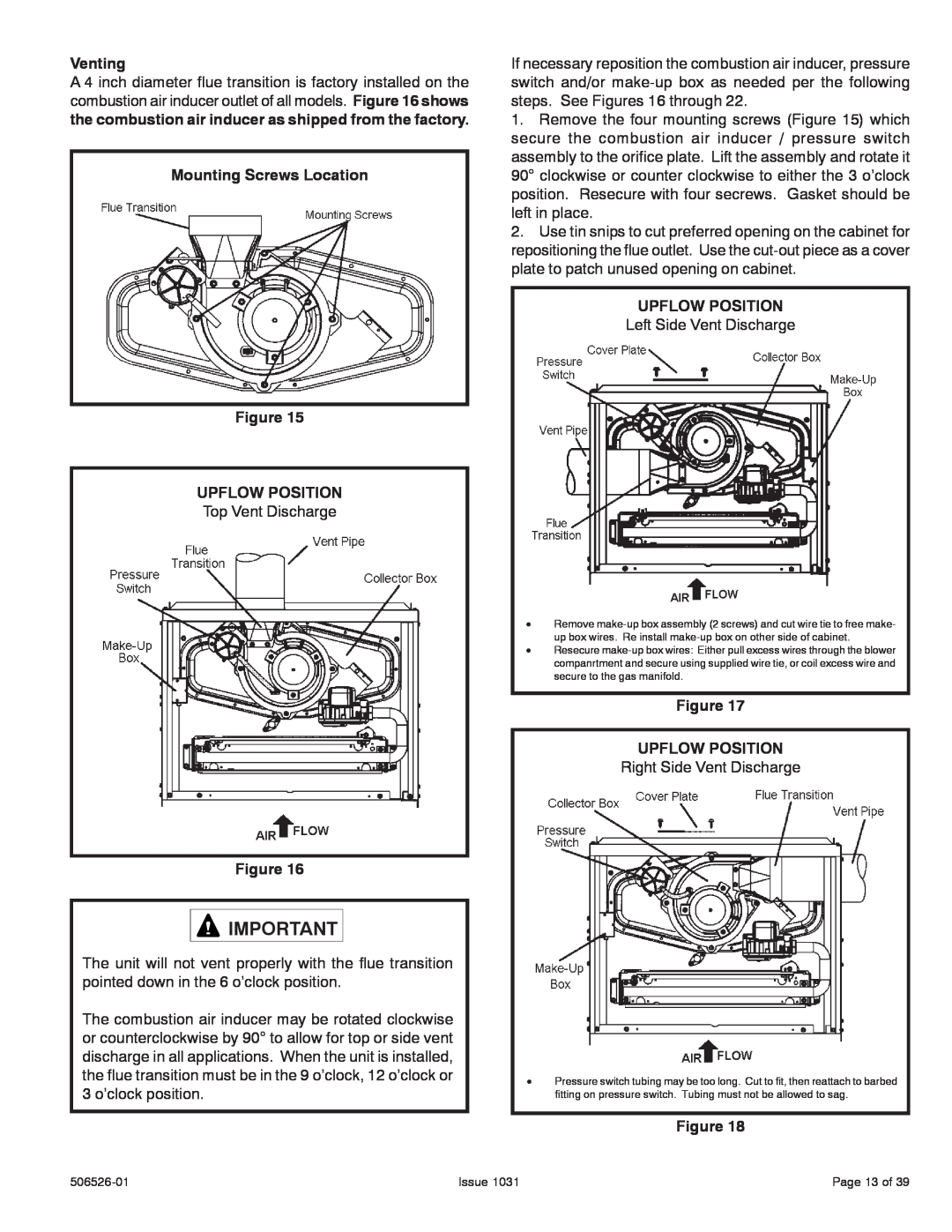
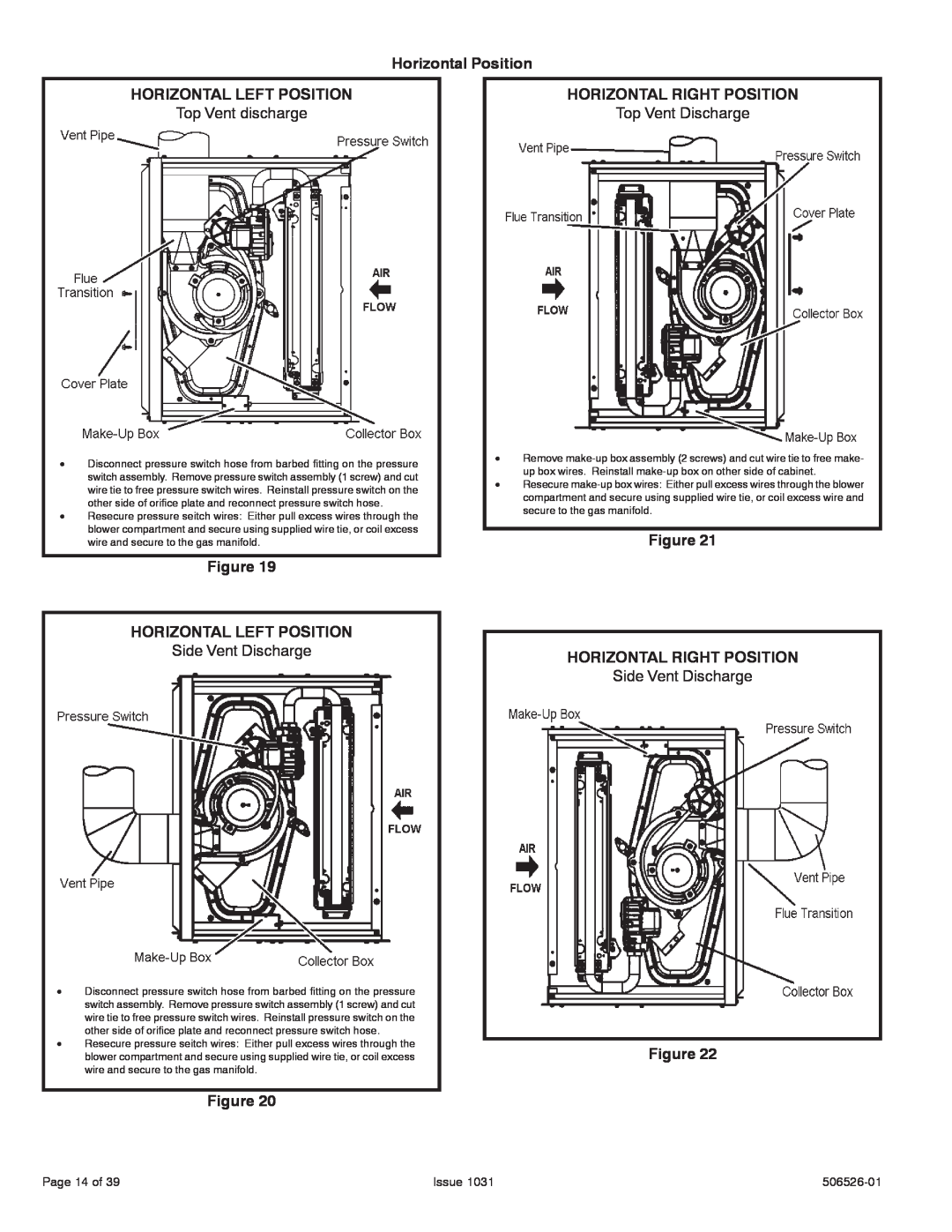
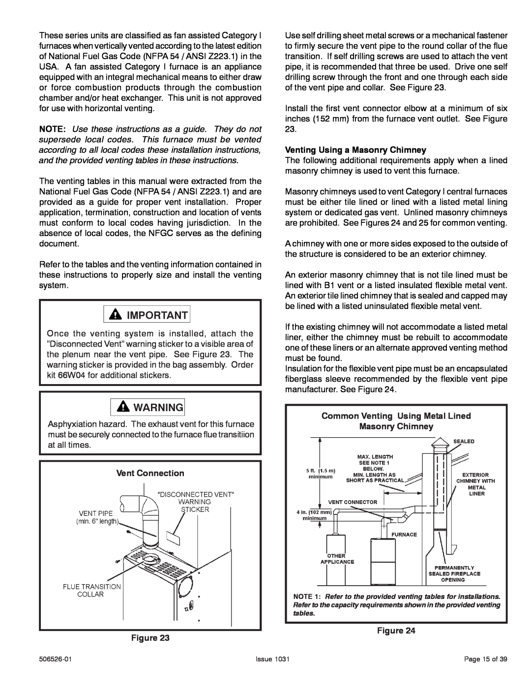
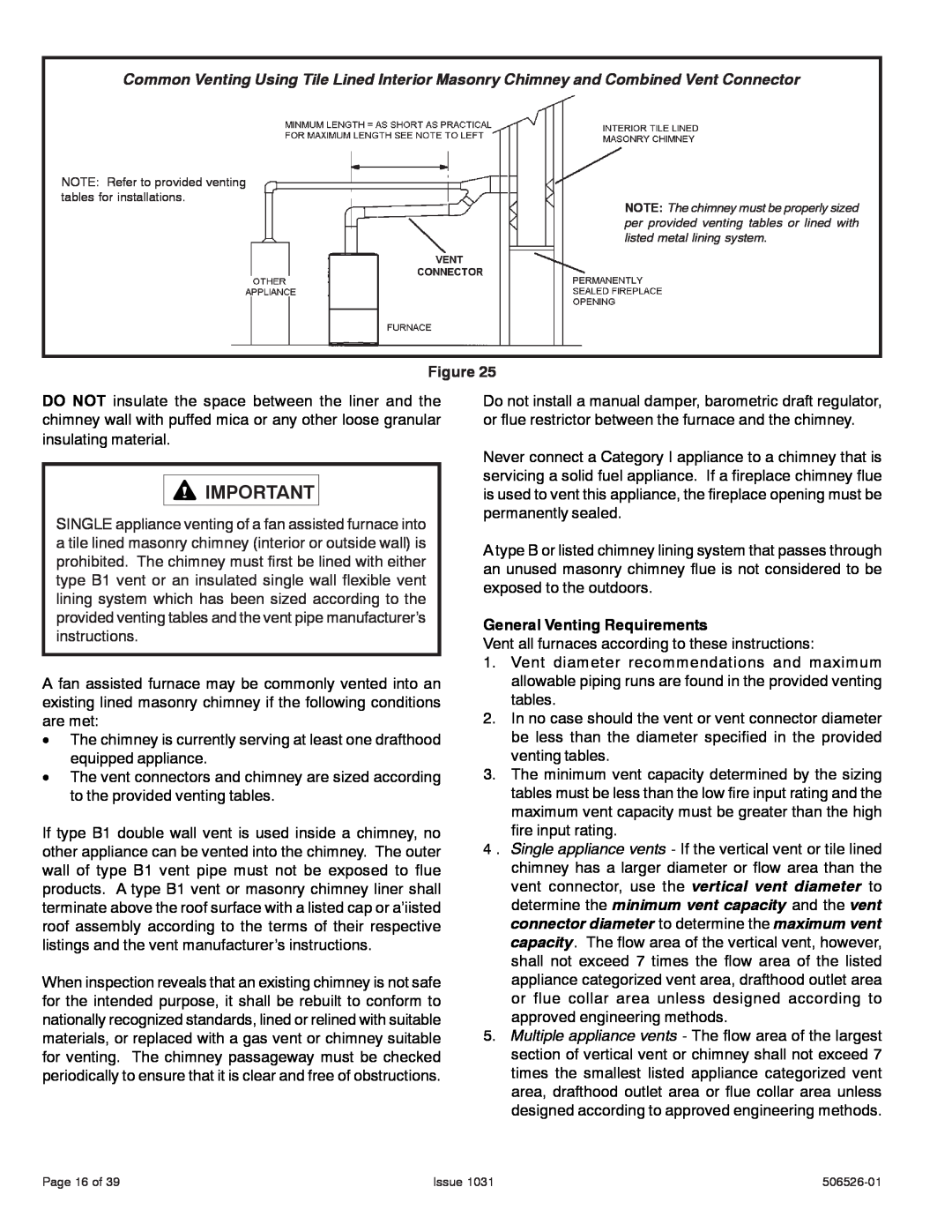
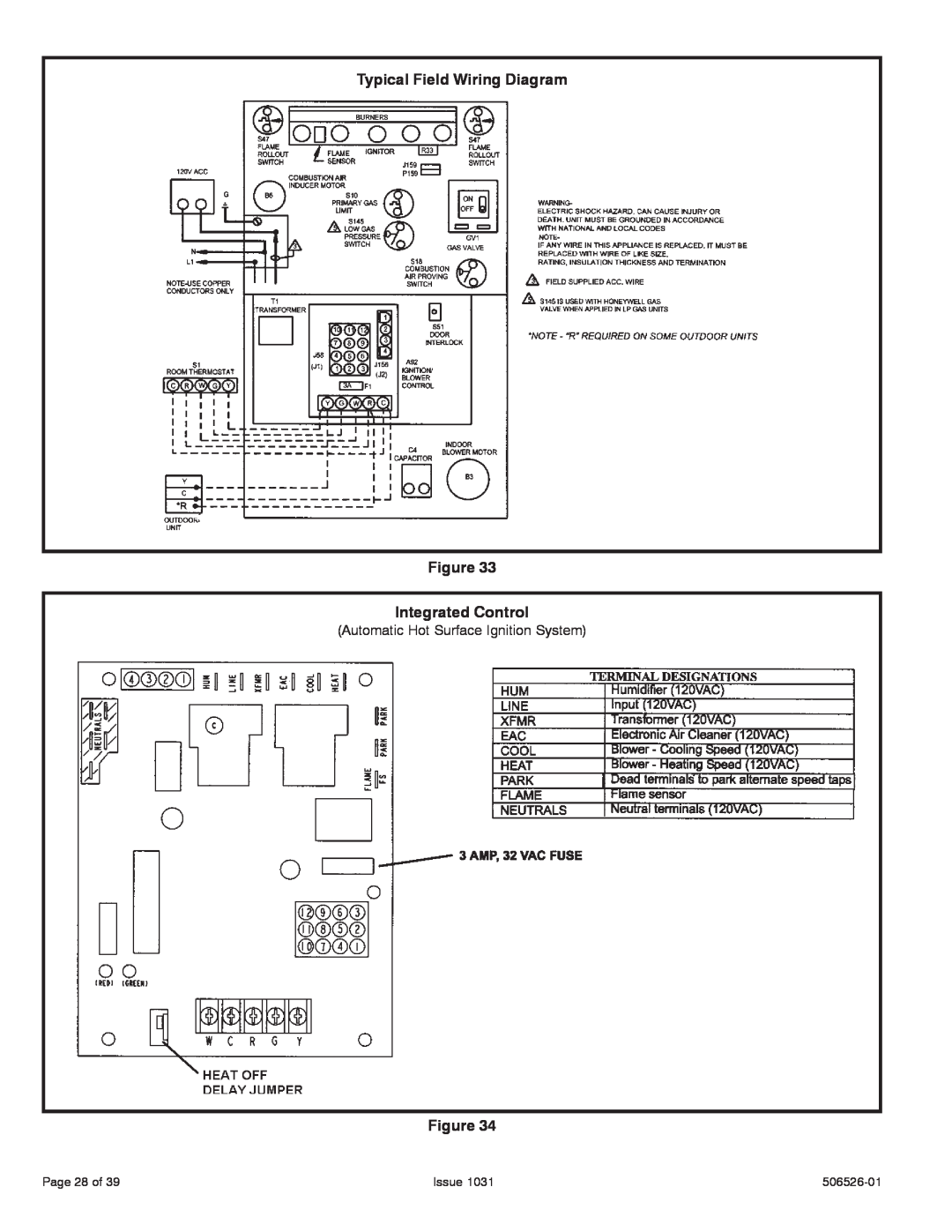
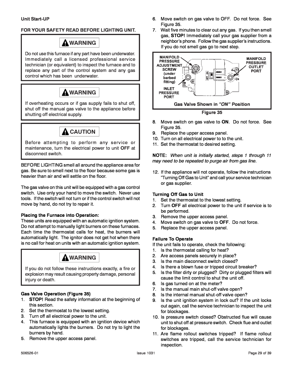
This furnace may be installed in either an attic or a crawl space. Either suspend the furnace from roof rafters or floor joists, as shown in Figure 13, or install the furnace on a platform, as shown in Figure 14.

Typical Horizontal Application

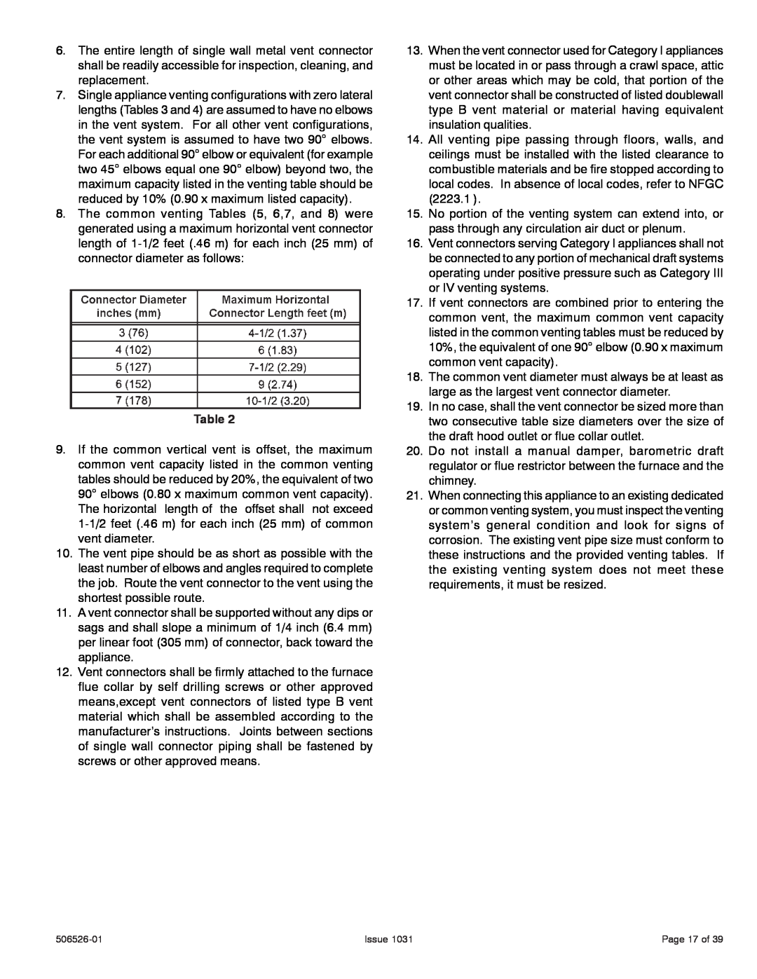
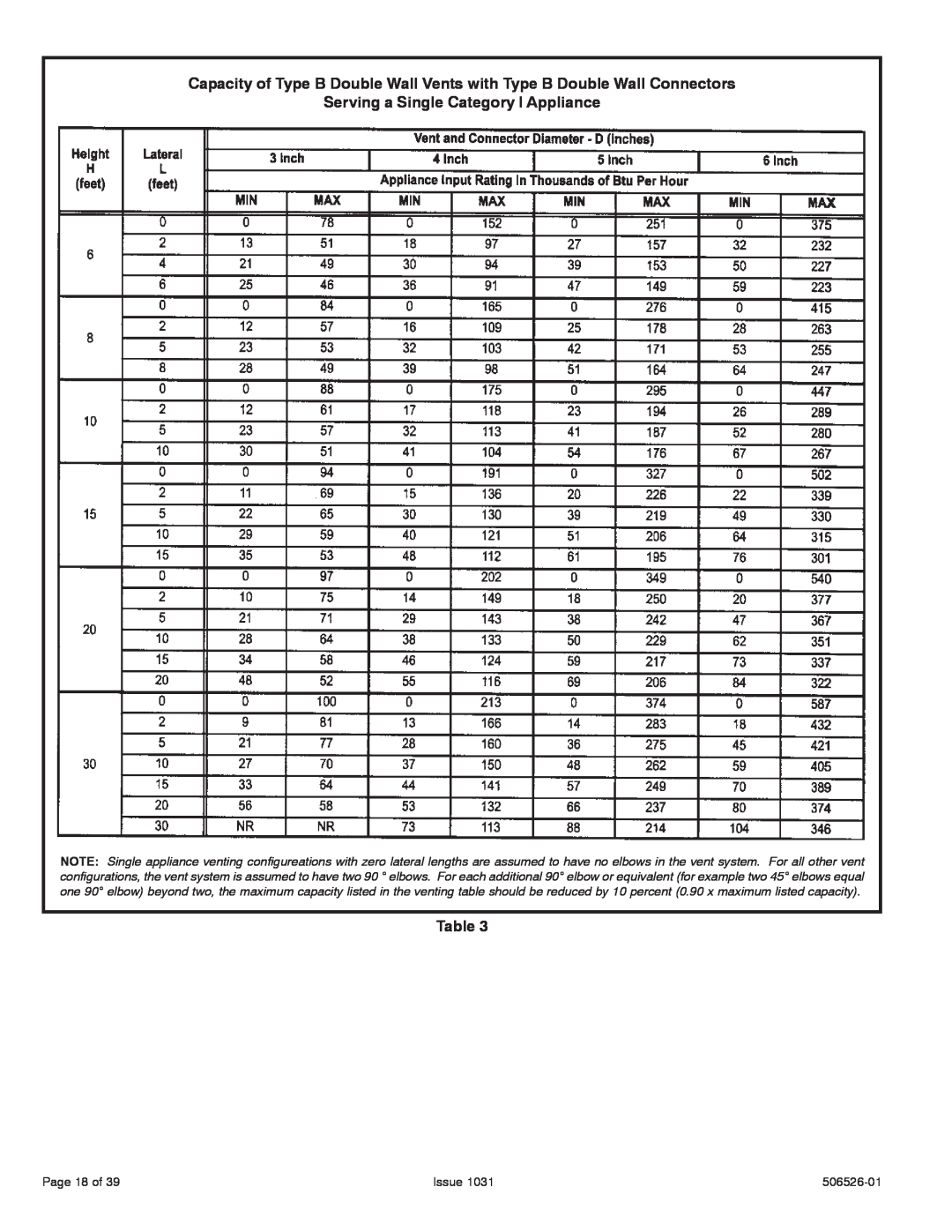
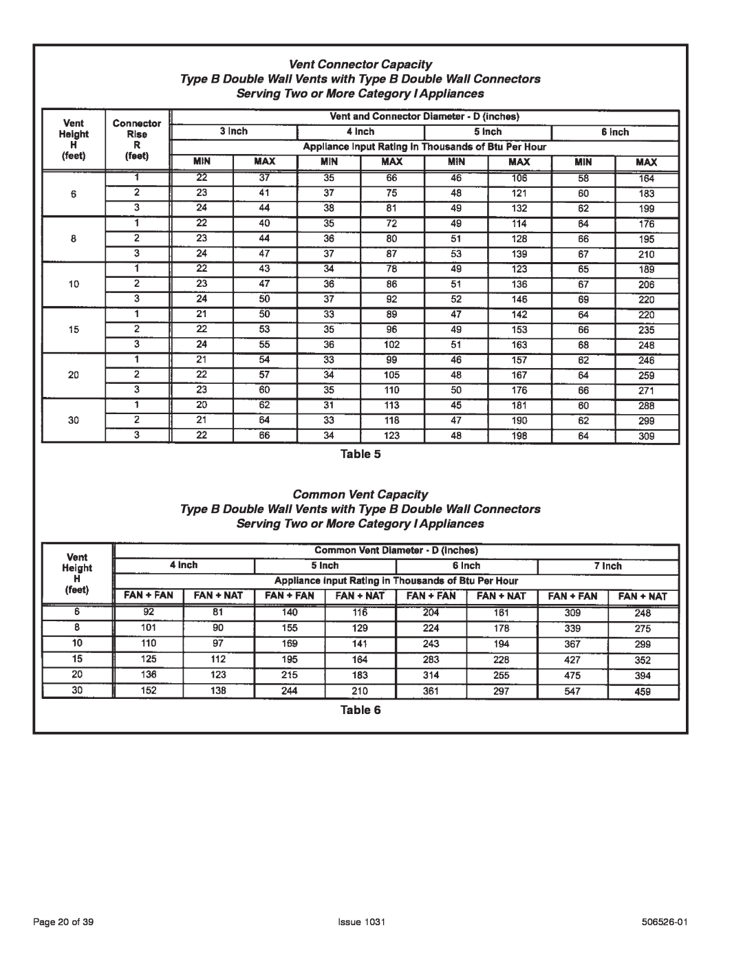
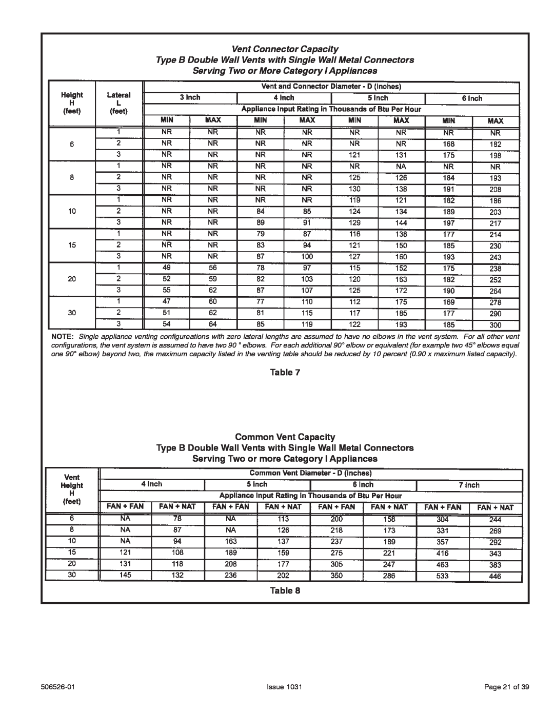
Unit Suspended in Attic or Crawlspace

Figure 13

NOTE: Heavy gauge perforated sheet metal straps may be used to suspend the unit from roof rafters or ceiling joists. When straps are used to suspend the unit in this way, support must be provided for both the ends. The straps must not interfere with the plenum or exhaust piping installation.

Cooling coils and supply and return air plenums must be supported separately.

NOTE: When the furnace is installed on a platform in a crawlspace, it must be elevated enough to avoid water damage and to allow the evaporator coil to drain.

Return Air - Horizontal Applications

Return air must be brought in through the end of a furnace installed in a horizontal application. The furnace is equipped with a removable bottom panel to facilitate installation. See Figure 11.

506526-01

Issue 1031

Page 11 of 39

Image 11
Contents Warm Air Gas Furnace TABLE OF CONTENTSINSTALLATION INSTRUCTIONS A80UH & 80G1UHSIDE VIEW A80UH & 80G1UH Unit Dimensions - inches mmFRONT VIEW 506526-01 A80UH & 80G1UHA80UH & 80G1UH Gas Furnace Safety InformationInstalled Locations DANGERUse of Furnace as a Construction Heater Installed in Combination with a Cooling CoilHeating Unit Installed Upstream of Cooling Unit Temperature Rise215 Metropolitan Drive West Columbia, SC GeneralProduct Contains Fiberglass Wool Allied Air Enterprises, IncFigure Air from Inside Unconfined SpaceConfined Space Equipment in Confined Space - All Air From InsideEQUIPMENT IN CONFINED SPACE Upflow Applications Setting EquipmentUpflow Application Installation Clearances 5.Bottom and one side return air Return Air - Upflow Applications1800 cfm 850 L/s must have one of the following 3.Bottom return air 4.Return air from both sidesHorizontal Applications Horizontal Application Installatioin clearancesRemoving the Bottom Panel Removing the Bottom Panel FigureSupply Air Plenum Horizontal Application Unit installed on PlatformFilters Table Duct SystemFigure UPFLOW POSITION VentingMounting Screws Location Figure UPFLOW POSITION UPFLOW POSITIONHORIZONTAL RIGHT POSITION Horizontal PositionHORIZONTAL LEFT POSITION Figure HORIZONTAL LEFT POSITIONIssue Venting Using a Masonry ChimneyCommon Venting Using Metal Lined Masonry Chimney Vent Connection FigureGeneral Venting Requirements Page 17 of Issue506526-01 Serving a Single Category I ApplianceIssue Page 18 of506526-01 Serving a Single Category I ApplianceIssue Page 19 ofServing Two or More Category I Appliances Vent Connector CapacityServing Two or More Category I Appliances Common Vent CapacityServing Two or More Category I Appliances Table Common Vent CapacityServing Two or more Category I Appliances Table Vent Connector CapacityPage 22 of Removal of the Furnace from Common VentCARBON MONOXIDE POISONING HAZARD IssueIssue Gas PipingGas Supply Gas Pipe Capacity - ft³/hr m³/hrPage 24 of Possible Gas Piping ConfigurationsFigure Horizontal Applications IssueINTERIOR MAKE-UPBOX INSTALLATION Figure INTERIOR MAKE-UPBOX INSTALLATION FigureLeak Check Figure Electrical ELECTROSTATIC DISCHARGE ESDCondensing Unit Thermostat Designations Accessory TerminalsGenerator Use - Voltage Requirements Thermostat506526-01 Wiring Diagram FigureIssue Page 27 ofAutomatic Hot Surface Ignition System Typical Field Wiring Diagram FigureIntegrated Control Gas Valve Operation Figure FOR YOUR SAFETY READ BEFORE LIGHTING UNITUnit Start-UP Placing the Furnace into OperationManifold Pressure Measurement Gas Pressure Adjustment Gas Flow ApproximateHeating Sequence Of Operation Figure Supply Pressure MeasurementPressure Switch Manifold Pressure Settings and Pressure SwitchOther Unit Adjustments Flame Rollout SwitchesElectronic Ignition Thermostat Heat AnticipationElectrical Blower SpeedsFlue And Chimney ServiceELECTRICAL SHOCK, FIRE OR EXPLOSION HAZARD Blower506526-01 Cleaning the Heat Exchanger and BurnersIssue Page 34 ofNOx INSERTS Figure Remove 5 Screws If NecessaryPage 36 of PLANNED SERVICEFAILURE CODES IssueControl Panel REPAIR PARTS LISTCabinet Parts Heating Parts506526-01 START-UP& PERFORMANCE CHECK LIST UNIT SET UPIssue Page 38 of506526-01 IssueUNIT OPERATION Page 39 of