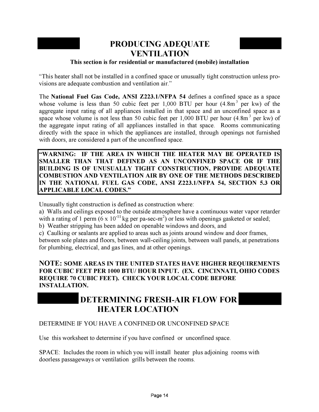
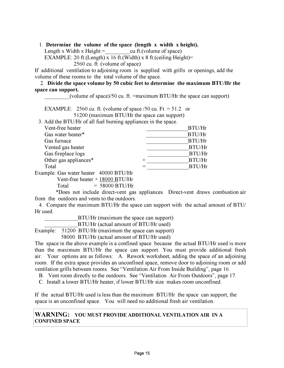
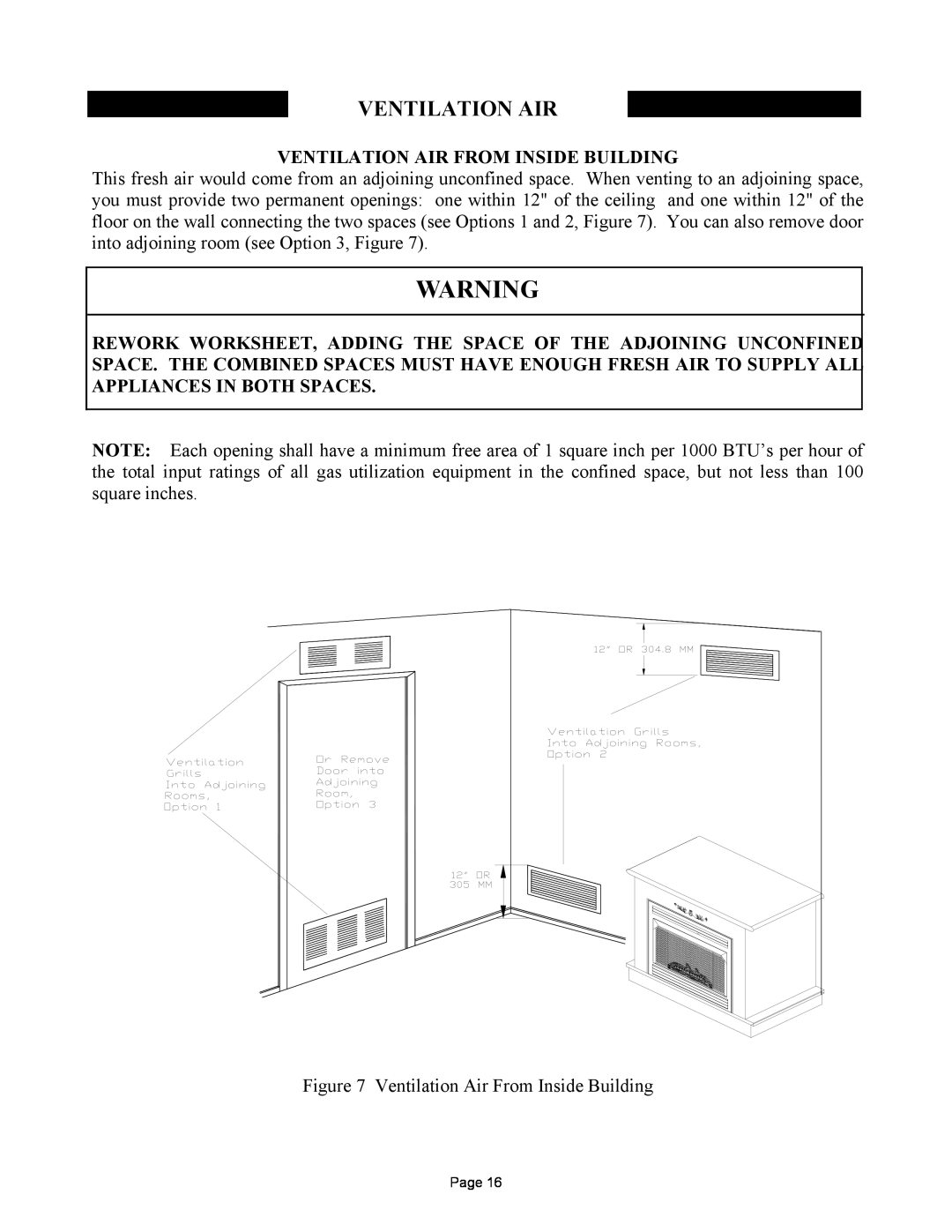
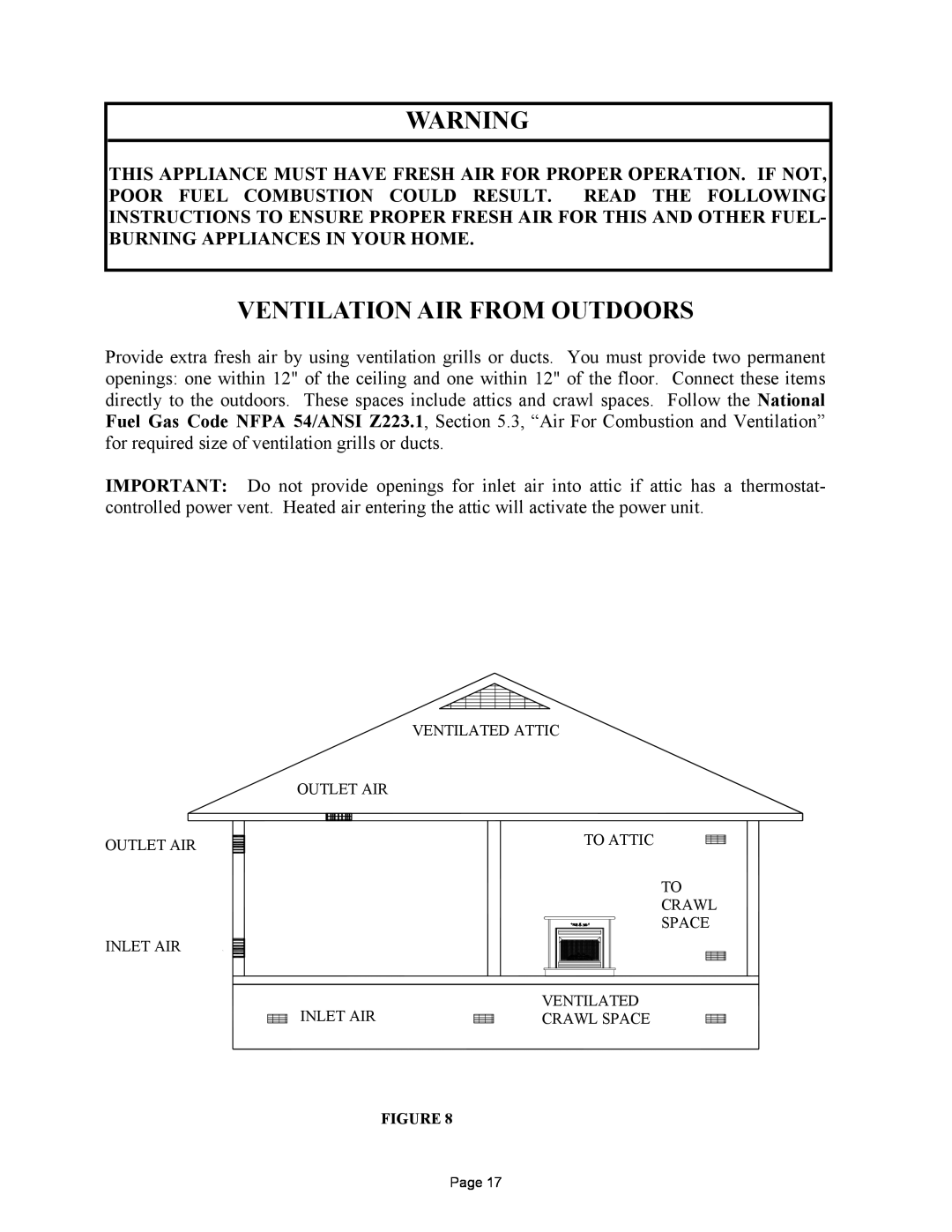
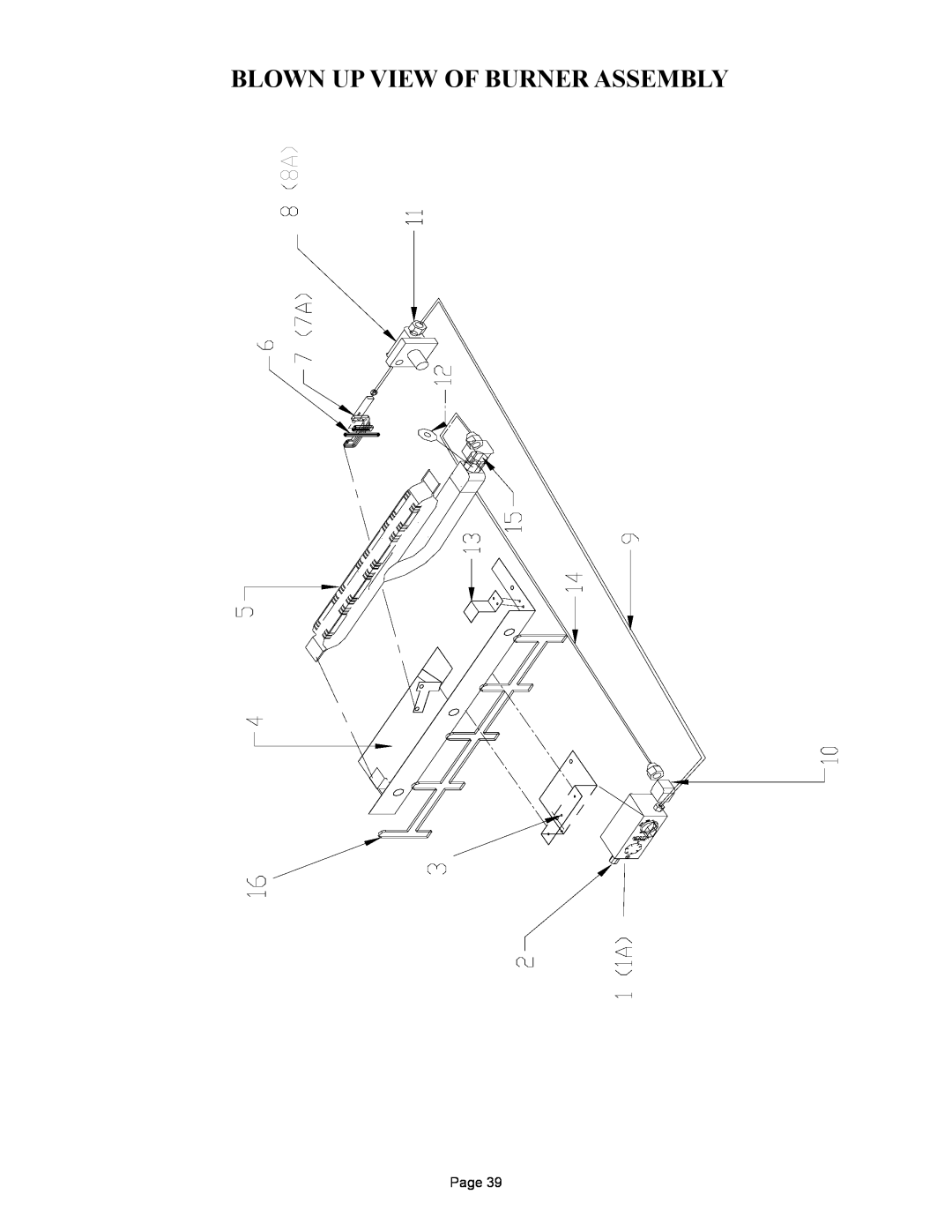
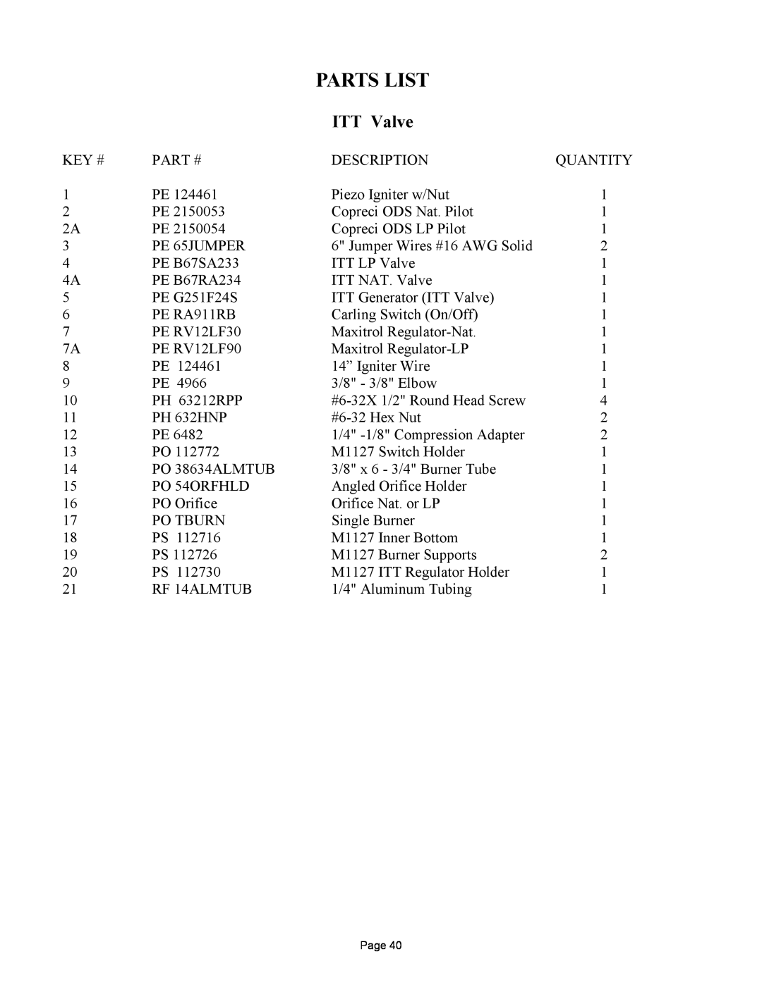
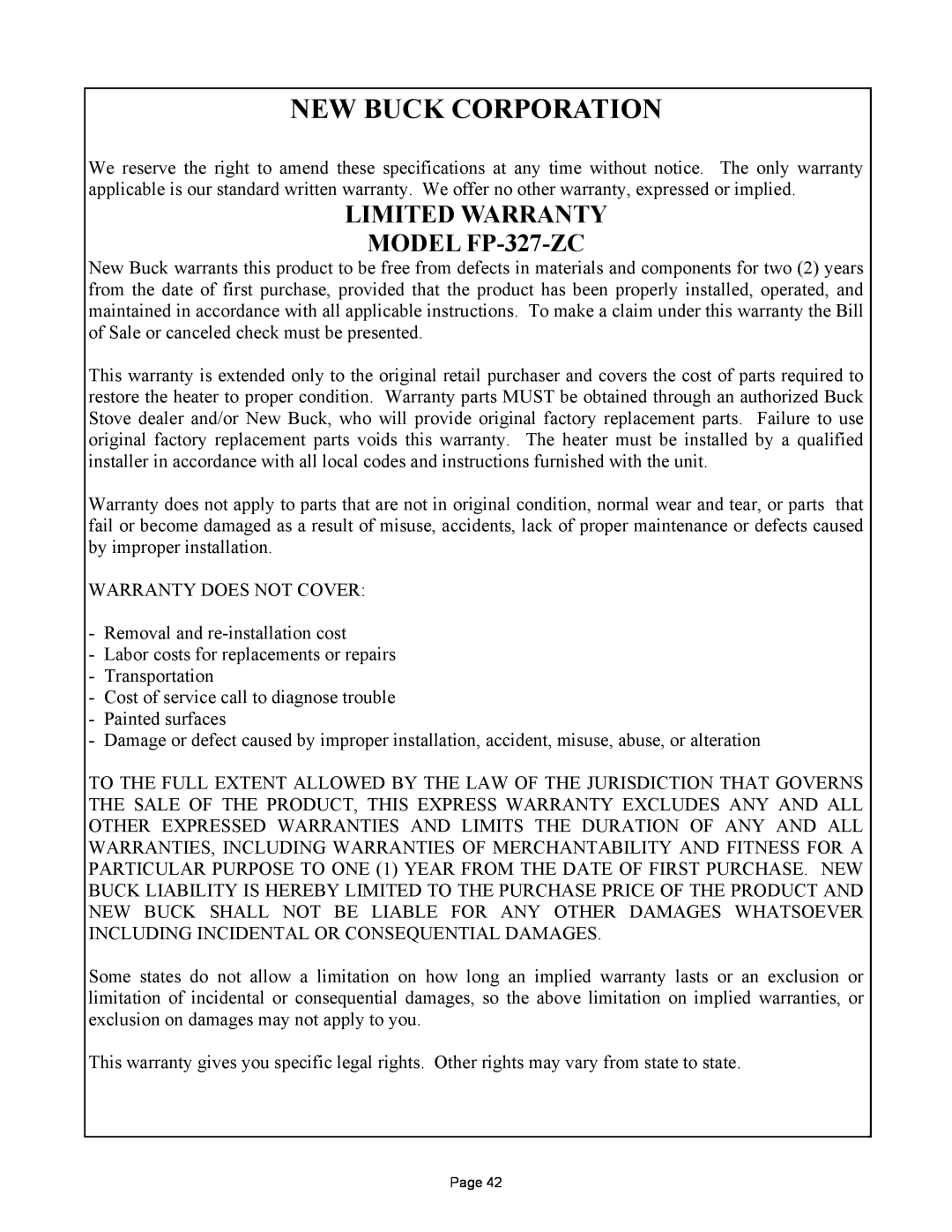
New Buck Corporation MODEL FP-327-ZC manual Lighting Instructions Millivolt Valve Itt

Page 23
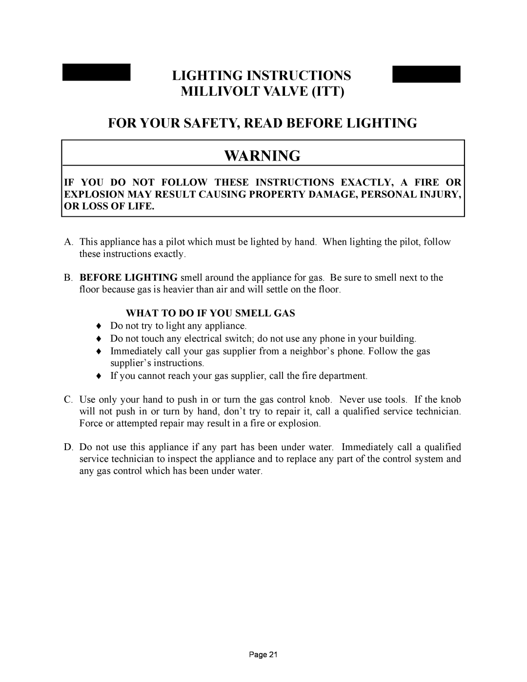
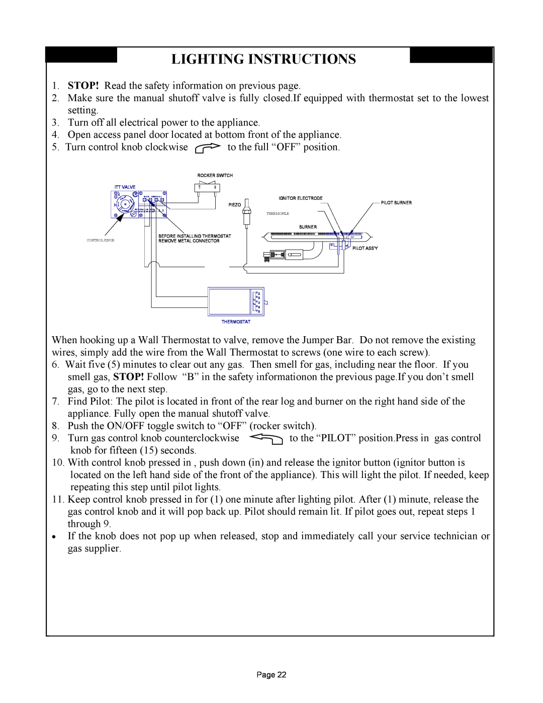
LIGHTING INSTRUCTIONS

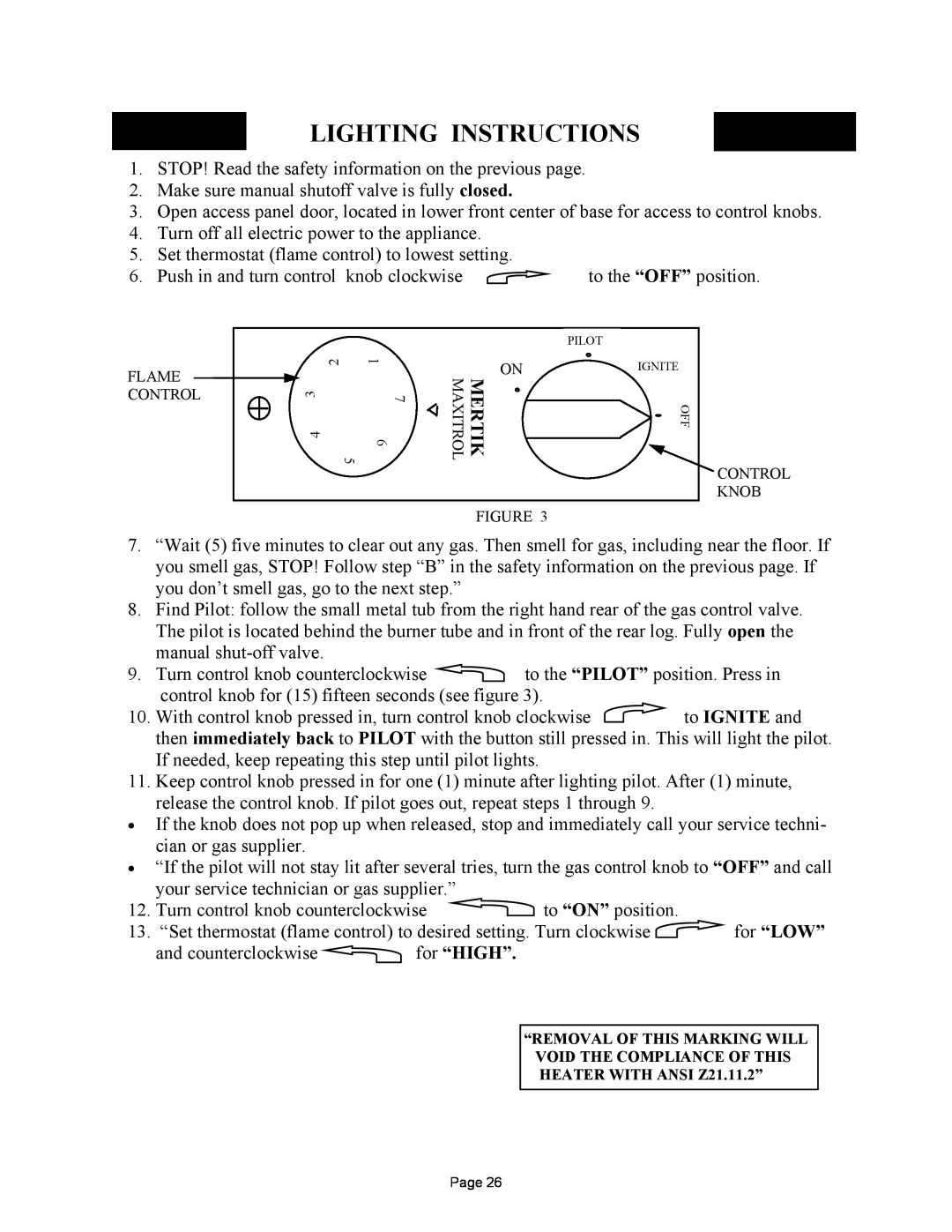
LIGHTING INSTRUCTIONS

MILLIVOLT VALVE (ITT)

FOR YOUR SAFETY, READ BEFORE LIGHTING

A.This appliance has a pilot which must be lighted by hand. When lighting the pilot, follow these instructions exactly.

B.BEFORE LIGHTING smell around the appliance for gas. Be sure to smell next to the floor because gas is heavier than air and will settle on the floor.

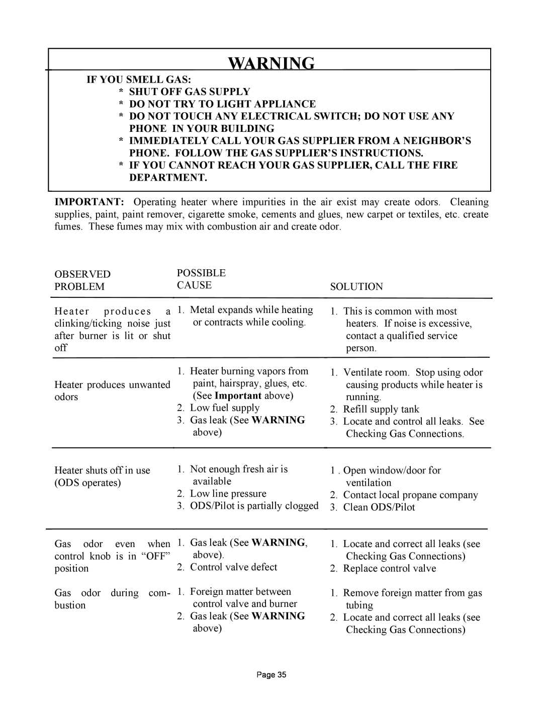
WHAT TO DO IF YOU SMELL GAS

Do not try to light any appliance.

Do not touch any electrical switch; do not use any phone in your building.

Immediately call your gas supplier from a neighbor’s phone. Follow the gas supplier’s instructions.

If you cannot reach your gas supplier, call the fire department.

C.Use only your hand to push in or turn the gas control knob. Never use tools. If the knob will not push in or turn by hand, don’t try to repair it, call a qualified service technician. Force or attempted repair may result in a fire or explosion.

D.Do not use this appliance if any part has been under water. Immediately call a qualified service technician to inspect the appliance and to replace any part of the control system and any gas control which has been under water.

Page 21
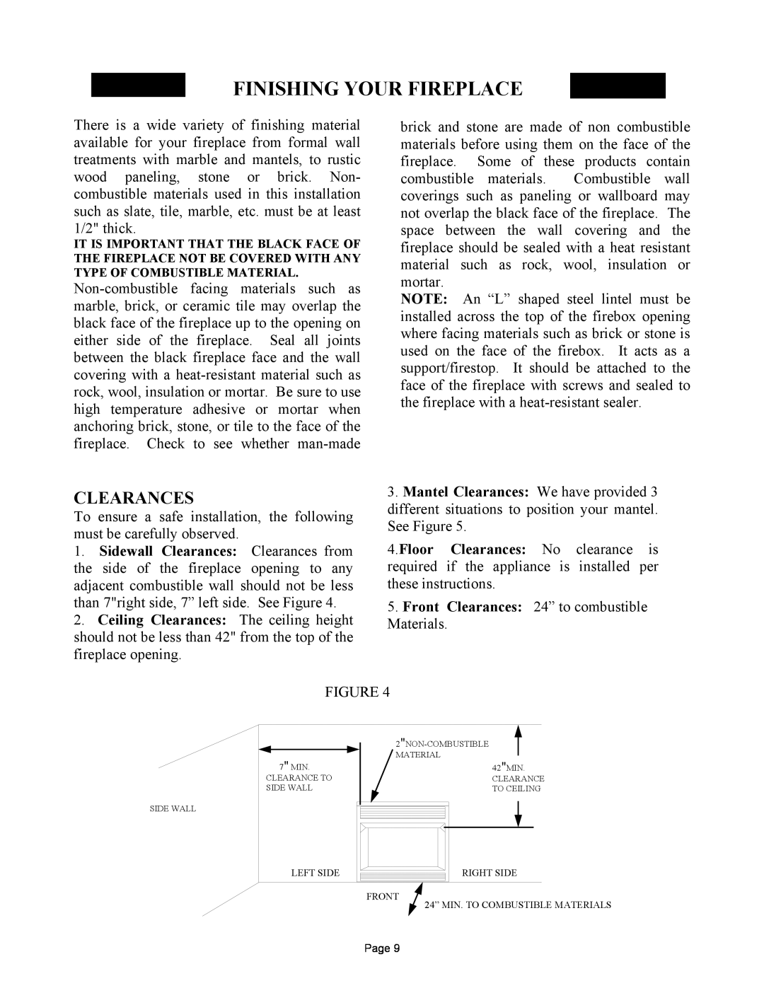
Image 23
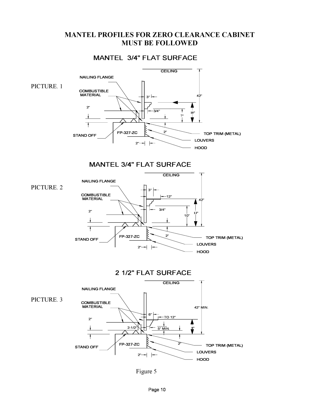
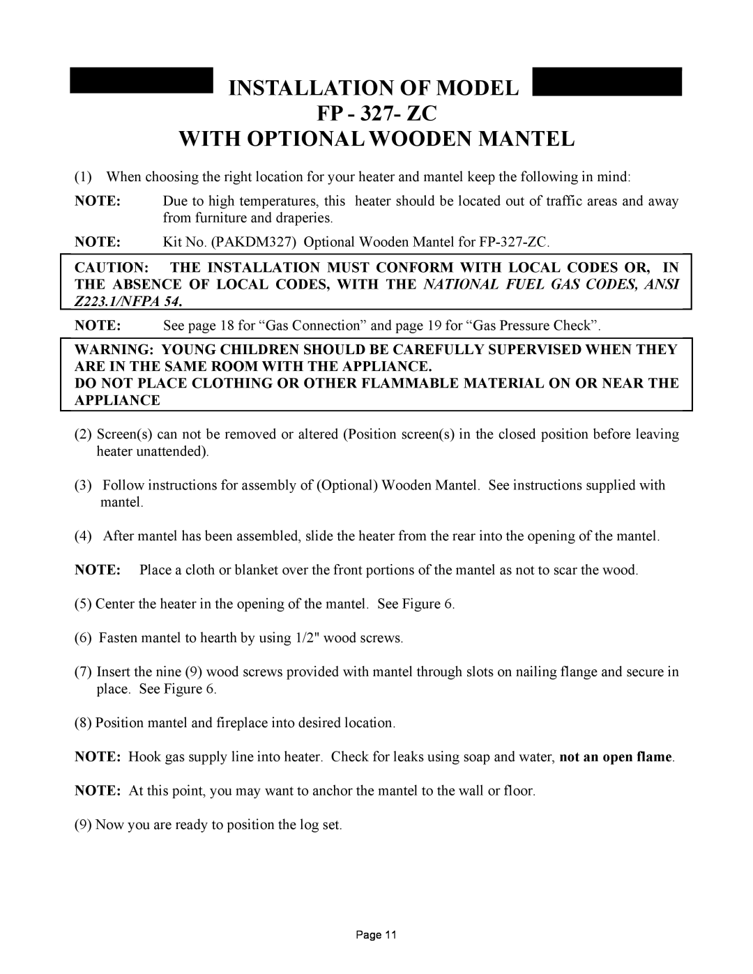
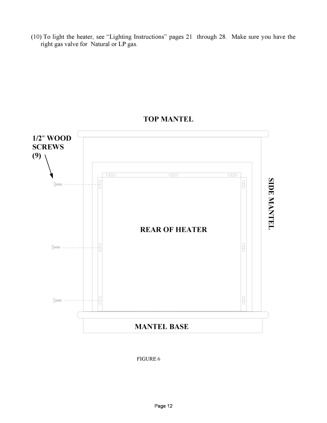
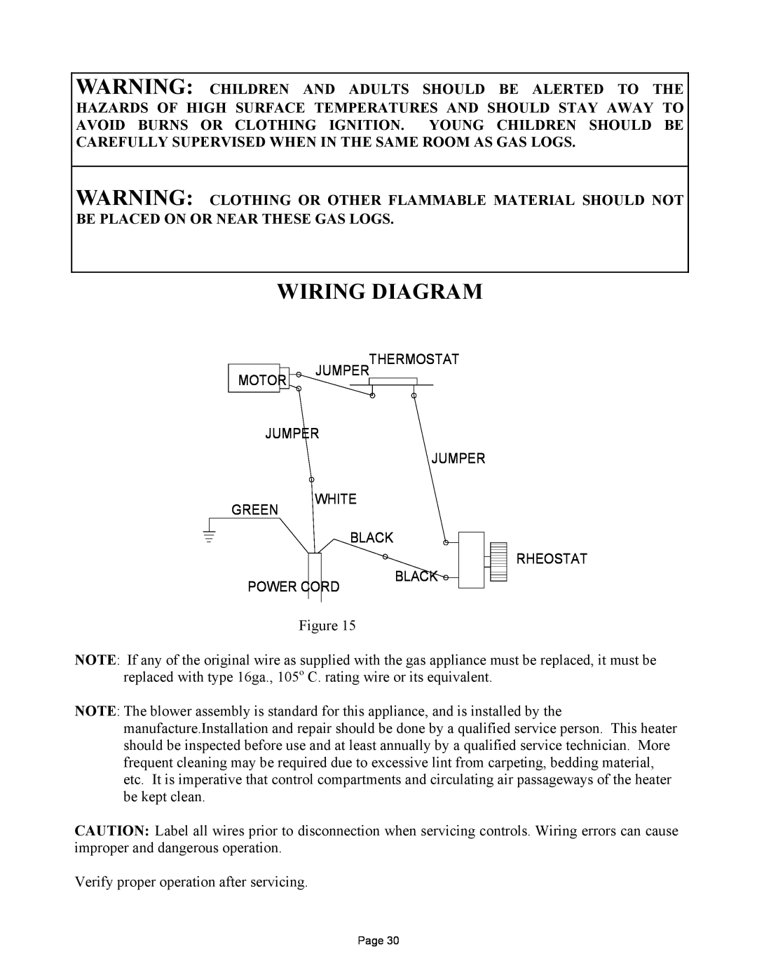
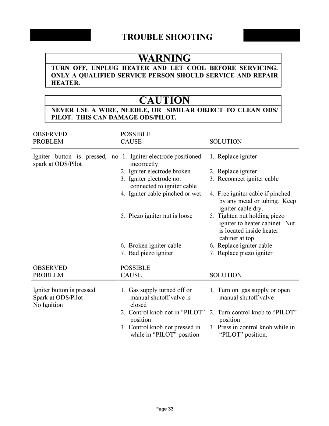
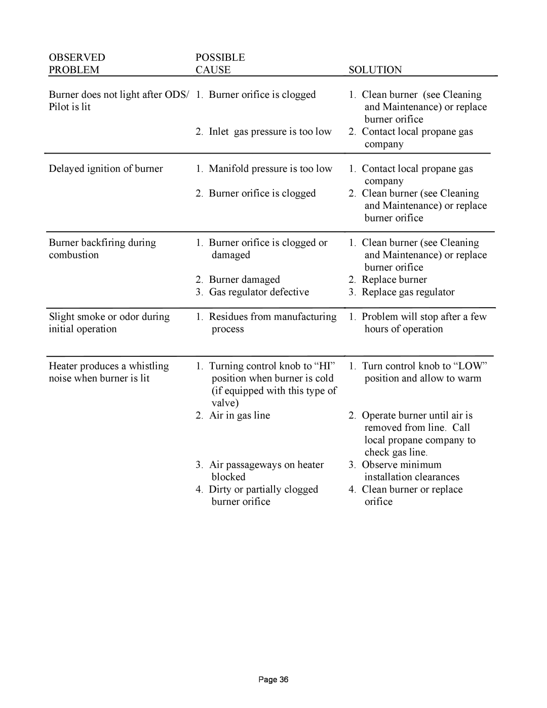
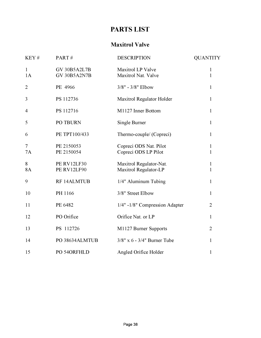
Contents 8000 Highway 226 South Spruce Pine, NC MODEL FP-327-ZCNEW BUCK CORPORATION Manufacturer NEW BUCK CORPORATION P.O. BoxPage TABLE OF CONTENTS Page SECTION I SAFETY INFORMATION WARNINGS Page Page DRAFTS SECTION ZERO CLEARANCE INSTALLATIONCHOOSING THE LOCATION FOR YOUR FIREPLACE GAS LINEPage Fireplace and Framing Dimensions inches3 1/4 7 1/2Framing the Firebox INSTALLING THE FIREBOXFIREPLACE CLEARANCES Install the FireboxCLEARANCES FINISHING YOUR FIREPLACEMANTEL 3/4 FLAT SURFACE MANTEL PROFILES FOR ZERO CLEARANCE CABINETMUST BE FOLLOWED MANTEL 3/4 FLAT SURFACEWITH OPTIONAL WOODEN MANTEL INSTALLATION OF MODEL FP - 327- ZCMANTEL BASE 1/2 WOOD SCREWSTOP MANTEL REAR OF HEATERSECTION AFTER MARKET MOBILE HOME INSTALLATION DETERMINING FRESH-AIRFLOW FOR HEATER LOCATION PRODUCING ADEQUATE VENTILATIONVent-freeheater VENTILATION AIR FROM INSIDE BUILDING VENTILATION AIRVENTILATION AIR FROM OUTDOORS FLAME GAS CONNECTIONGAS PRESSURE CHECK PLACEMENT OF LOGSSEE DIAGRAM ON PAGE Page PLACEMENT OF LOGS3 1 2 Figure WHAT TO DO IF YOU SMELL GAS FOR YOUR SAFETY, READ BEFORE LIGHTINGLIGHTING INSTRUCTIONS MILLIVOLT VALVE ITT Page ROCKER SWITCHBEFORE INSTALLING THERMOSTAT REMOVE METAL CONNECTORPage IGNITOR ELECTRODEPILOT BURNER THERMO--COUPLEPILETHERMOSTAT CONTROL OPERATION MANUAL LIGHTING PROCEDUREFOR YOUR SAFETY, READ BEFORE LIGHTING LIGHTING INSTRUCTIONS MODULATING VALVEMAXITROLfor “HIGH” LIGHTING INSTRUCTIONSto IGNITE and for “LOW”TO TURN OFF GAS TO APPLIANCE IGNITER ELECTRODE THERMO-COUPLEO.D.S PILOT BURNER THERMOSTAT CONTROL OPERATION MANUAL LIGHTING PROCEDUREPROPANE PILOT FLAME CHECKNATURAL PILOT BURNERWIRING DIAGRAM Page NOTE #PESBRO84 Blower Model FP-327-ZCRating 120 volts/60HZ/0.54 Amps CLEANING IMPORTANT SAFEGUARDSTROUBLE SHOOTING Air in gas lines when OBSERVED PROBLEM OBSERVED SERVICING REPAIR PARTSMaxitrol Valve PARTS LISTPage BLOWN UP VIEW OF BURNER ASSEMBLYPARTS LIST ITT ValvePage BLOWN UP VIEW OF BURNER ASSEMBLYPage Page