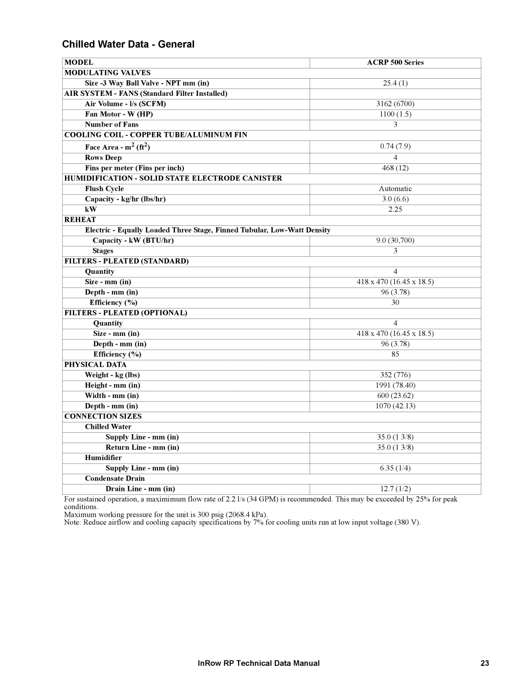
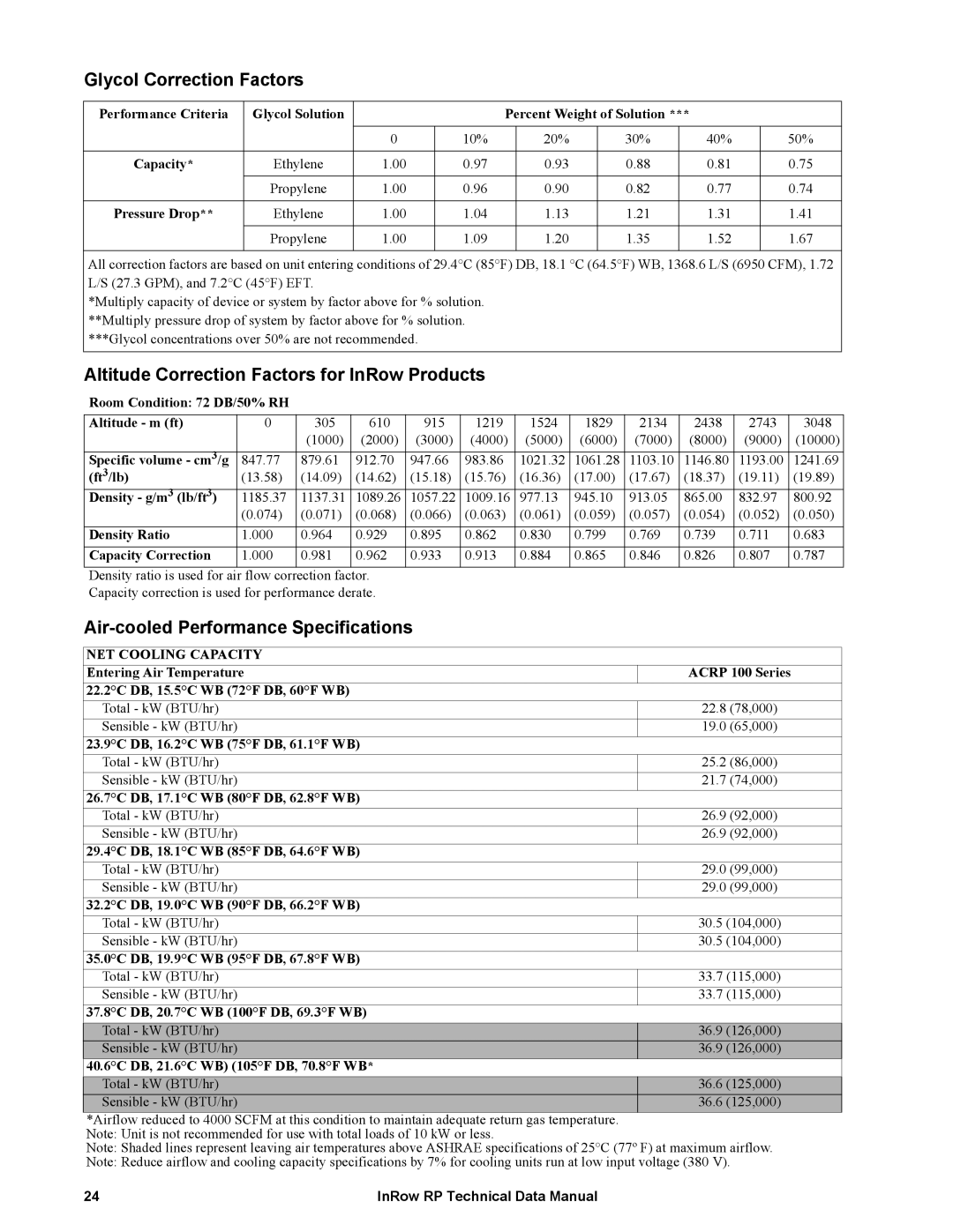
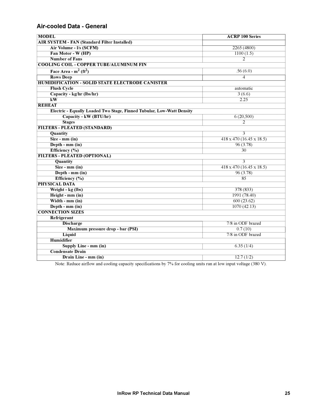
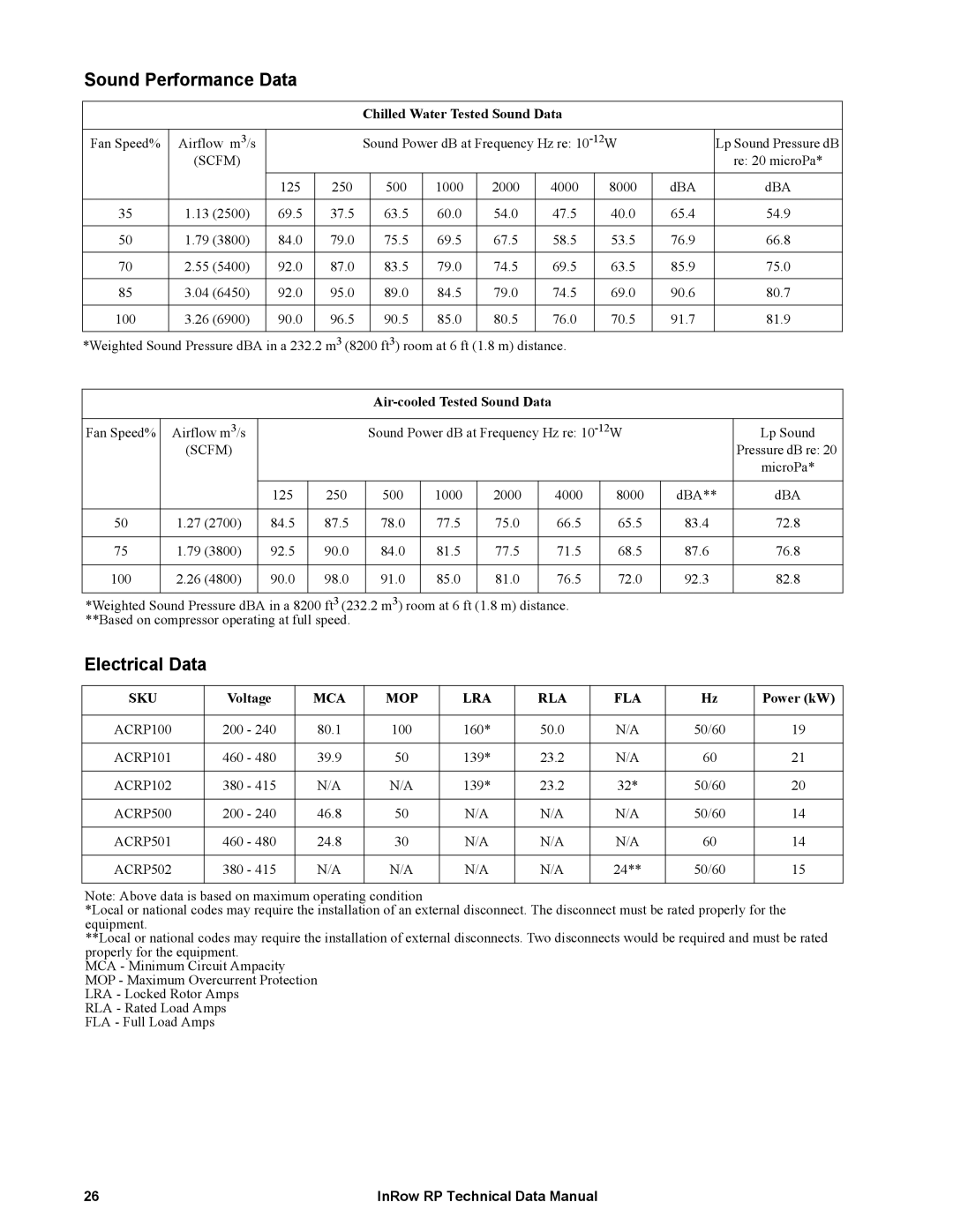
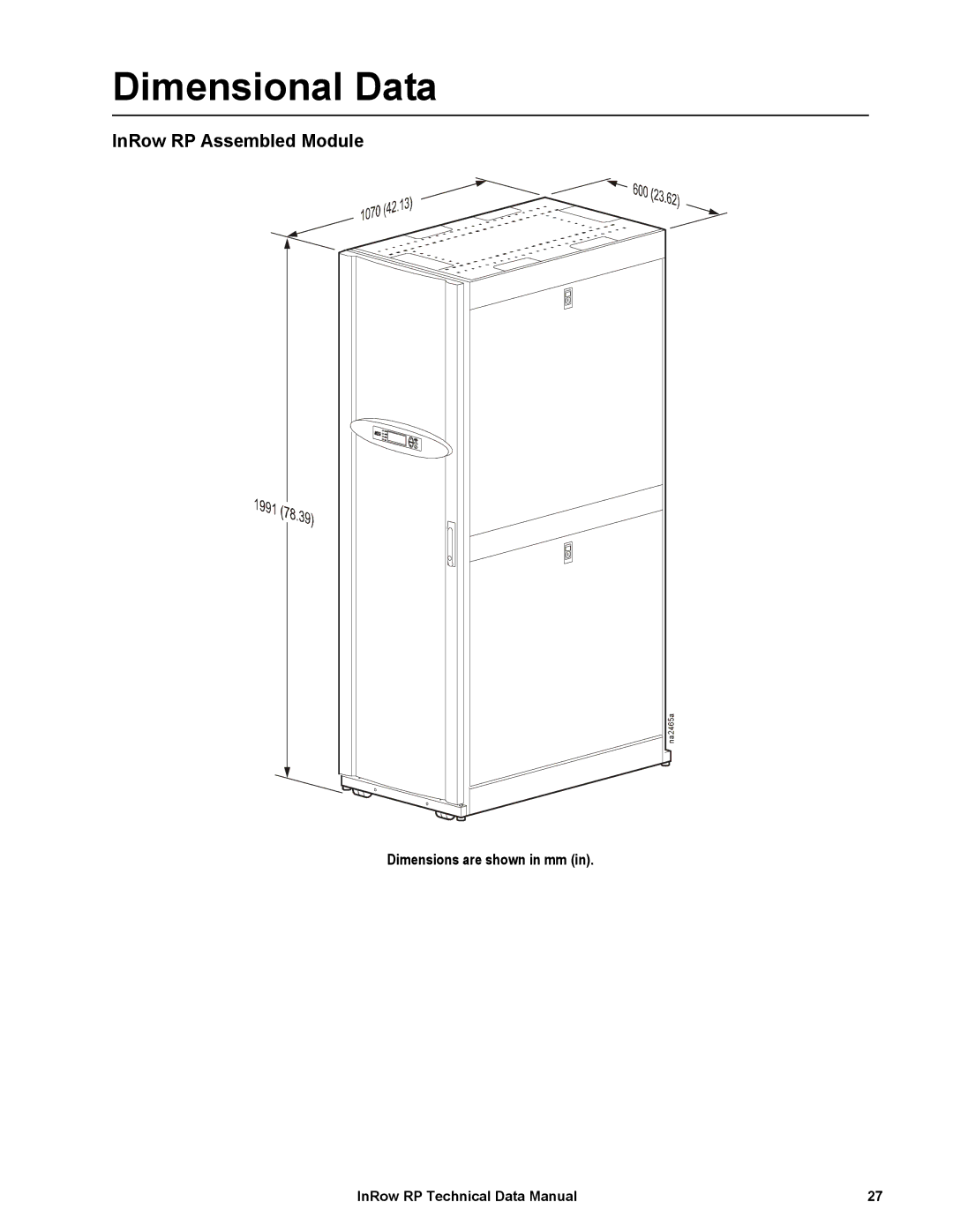
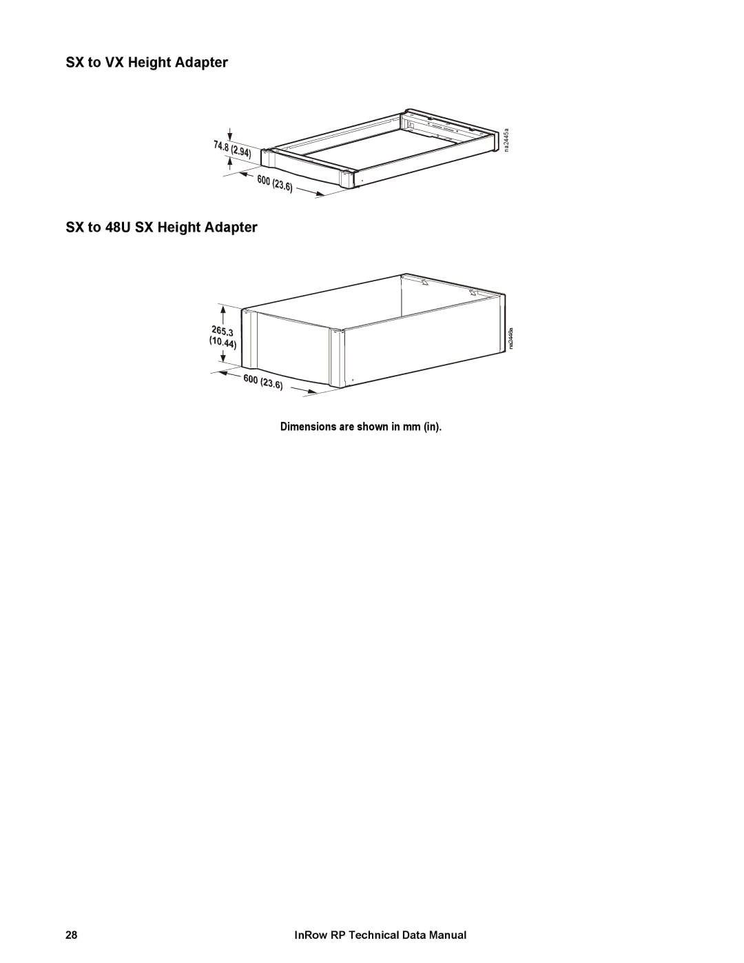
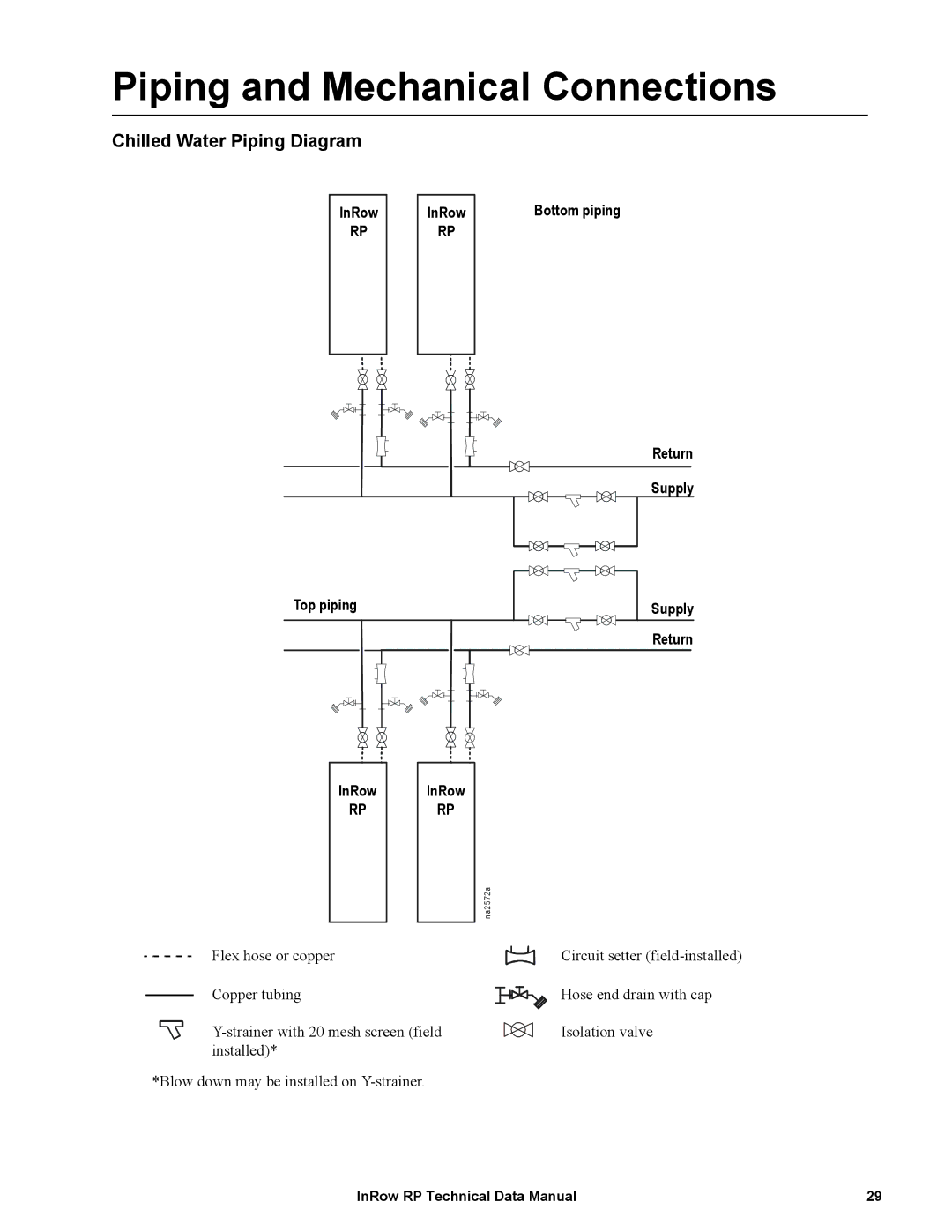
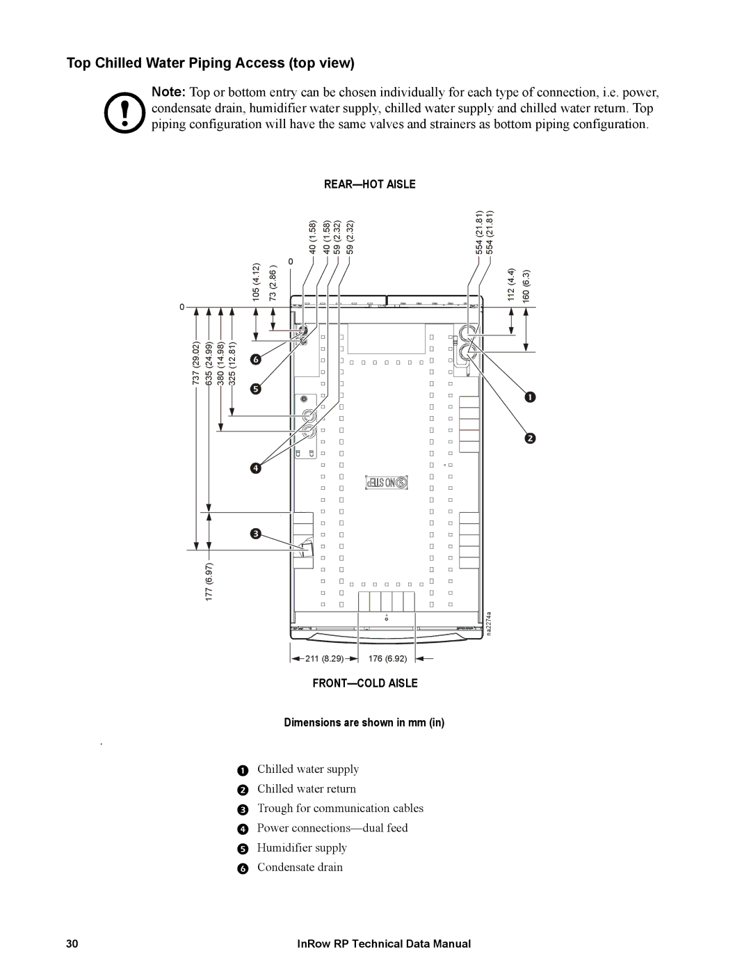
ACRP502, ACRP500, ACRP501, ACRP102, ACRP101 specifications
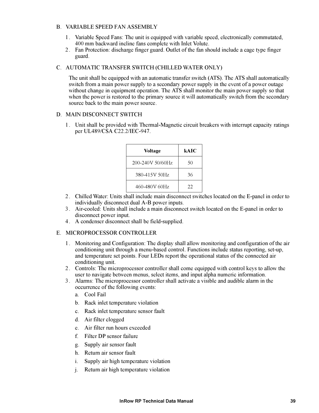
The APC ACRP series, consisting of models ACRP100, ACRP101, ACRP102, ACRP501, and ACRP500, represents a significant innovation in power distribution and protection. These compact, reliable, and efficient solutions are designed specifically for critical applications in data centers, industrial environments, and commercial facilities.The ACRP100 is the entry-level model, providing essential features for basic power monitoring and control. It incorporates advanced metering capabilities, enabling users to monitor voltage, current, and power consumption in real-time. The ACRP100's user-friendly interface allows for easy navigation, making it an ideal choice for small to medium-sized installations that require fundamental power management.
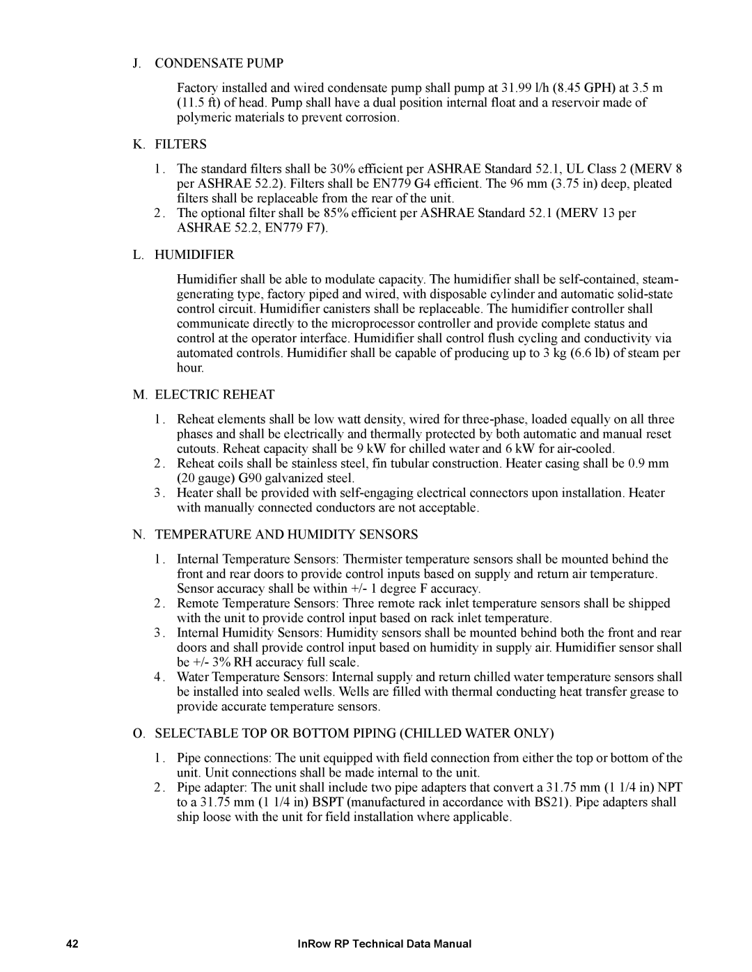
Stepping up, the ACRP101 enhances functionality with added remote monitoring capabilities. This model introduces smart connectivity features, allowing users to access critical data from anywhere through a secure mobile application or web-based platform. With its ability to integrate seamlessly with other APC systems, the ACRP101 is tailored for environments seeking improved operational visibility and proactive maintenance.
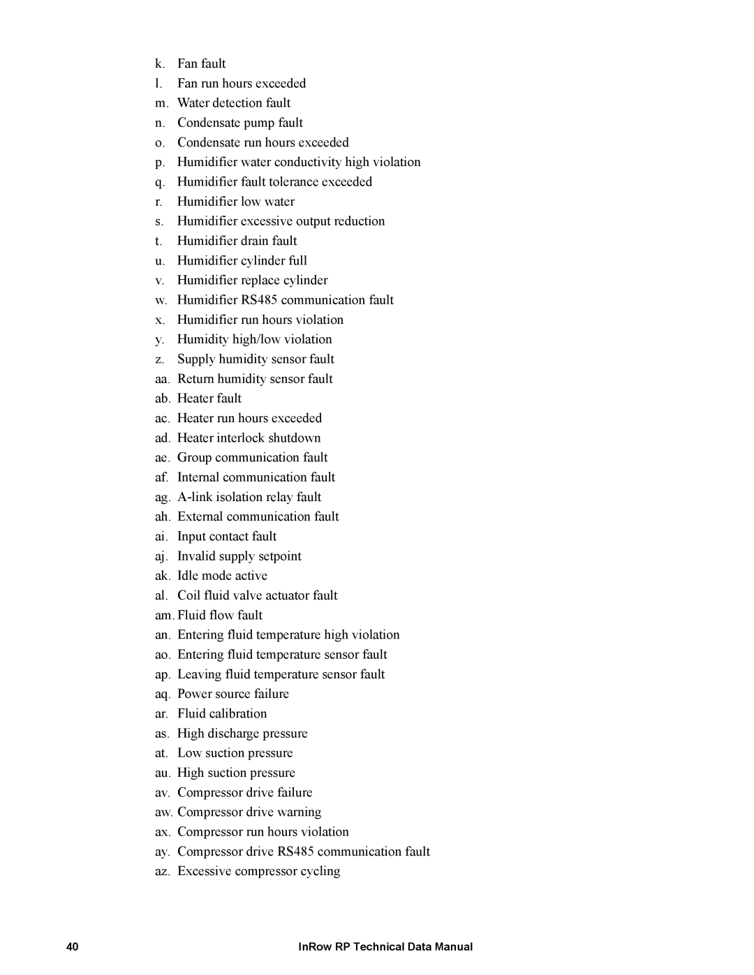
The ACRP102 takes a further leap by integrating advanced predictive analytics. This model uses machine learning algorithms to analyze data trends, predicting potential failures before they occur. By minimizing downtime and optimizing maintenance schedules, the ACRP102 becomes a vital tool for organizations focused on reliability and efficiency.
In the higher-end range, the ACRP501 offers robust power management features, including enhanced surge protection and redundancy capabilities. This model is ideal for mission-critical operations where every second counts. It supports a wide range of input voltages and can manage multiple power sources concurrently, ensuring uninterrupted power supply in fluctuating conditions.
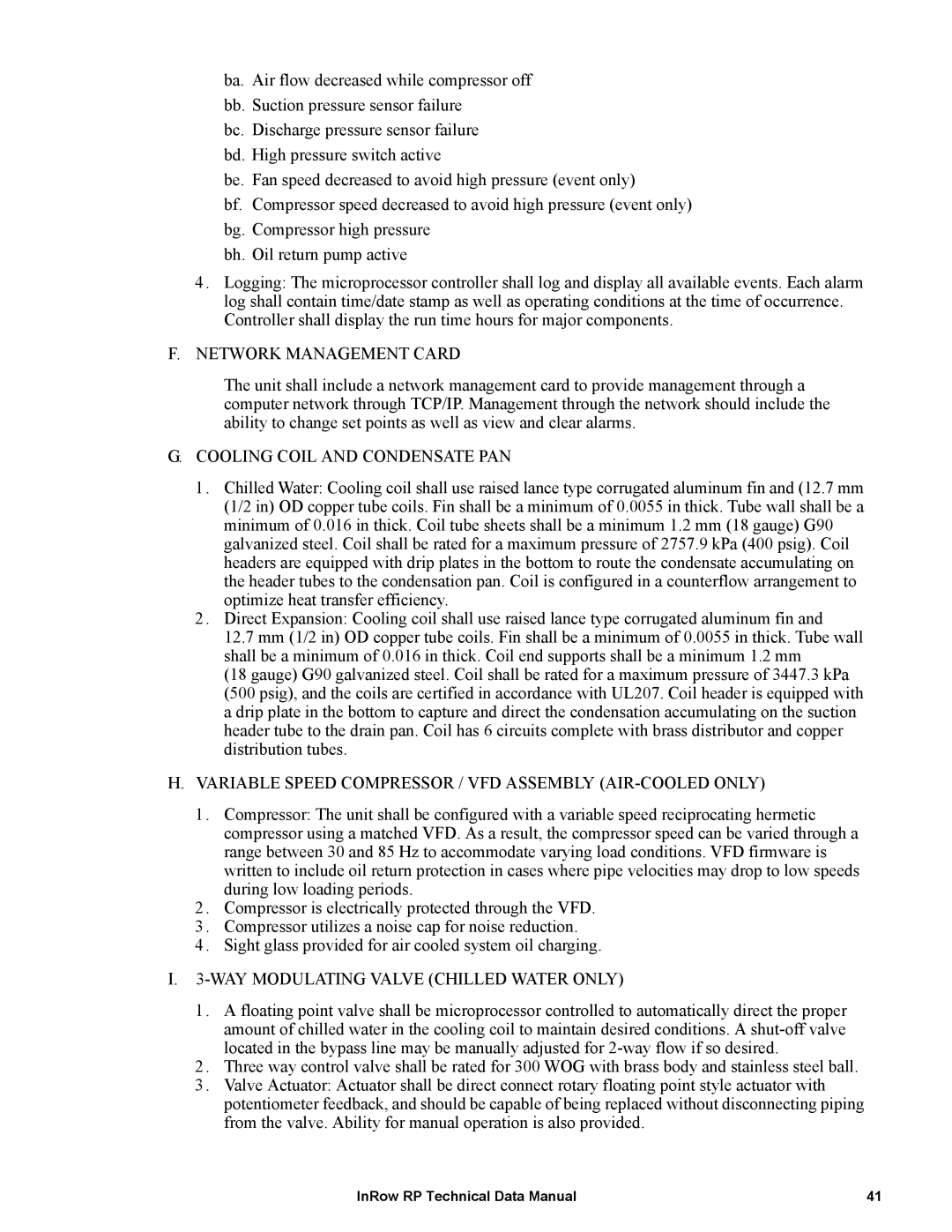
Lastly, the ACRP500 combines all the leading features of the series, focusing on scalability and flexibility. This model is engineered to adapt to evolving infrastructure needs, supporting modular configurations that can grow with the organization. Its extensive reporting functions and customizable dashboards provide clear insights into power usage and performance metrics, empowering facility managers to make informed decisions.
In summary, the APC ACRP series provides a comprehensive suite of solutions for power management, tailored to meet diverse operational needs. From basic monitoring with the ACRP100 to the predictive capabilities of the ACRP102 and the advanced functionalities of the ACRP500, these models collectively offer enhanced reliability, efficiency, and scalability while ensuring optimal protection for critical applications.
