B. Pinpointing the Buried Fault
Step 1. Connect the 3M™ Earth Contact Frame to the External Jack [15] ([14] for 2550) of the receiver using the Earth Contact Frame cable (4 ft. (1.2 m) cable).
Step 2. Press On/Off [1] to power on the receiver. The receiver display screen will display "Fauly Calibrating" for about 5 seconds.
Step 3. Press Menu/OK [5].
Step 4. Press Fault [SK] to select Fault mode.
Step 5. Hold the receiver in one hand and the Earth Contact Frame in the other with the solid
Step 6. Press REF [SK] to record the fault Signal Strength [9] ([8] for 2550 locator) level reference. The signal level will be recorded in the box above REF [SK] on the display. This reference indicates the Signal Strength [9] ([8]) for 2550 locator) level at the ground rod. When the operator reaches the major fault location, the Signal Strength [9] ([8]) for 2550 locator) indicated on the receiver will be very close (within 12dB) to this reference signal strength level.
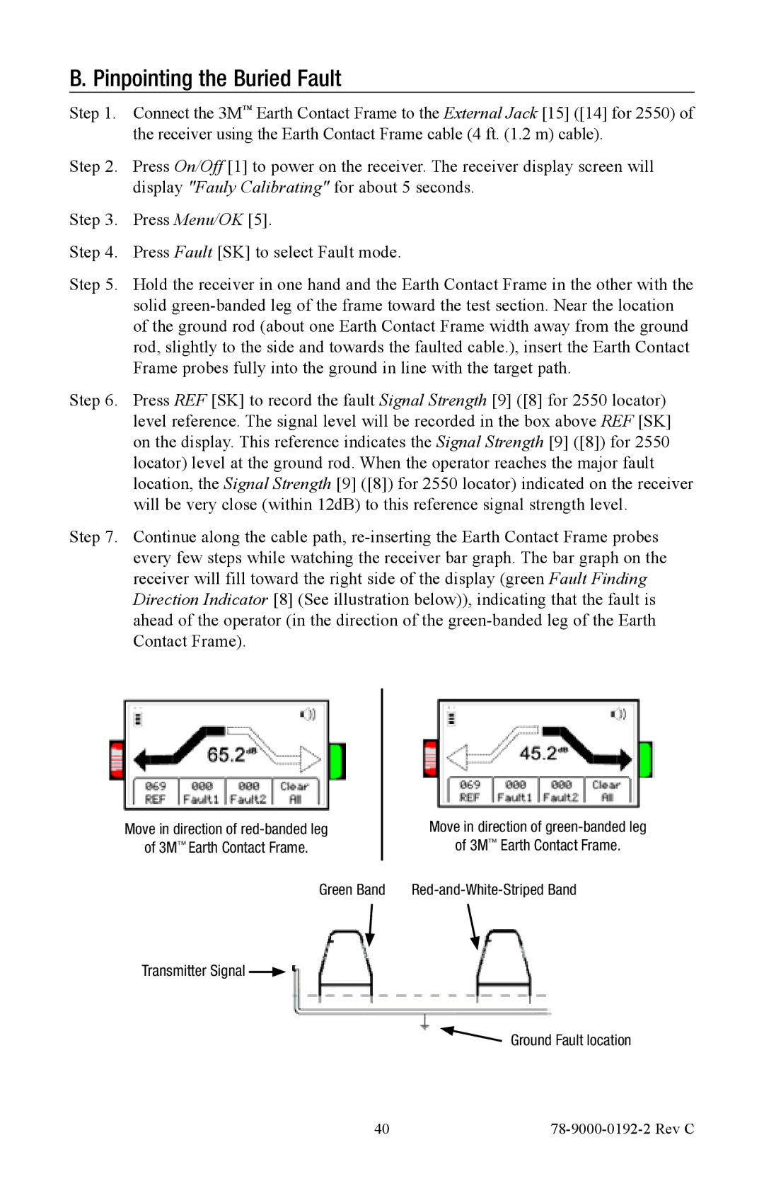
Step 7. Continue along the cable path,
Move in direction of |
| Move in direction of | ||
of 3M™ Earth Contact Frame. |
| of 3M™ Earth Contact Frame. | ||
|
| Green Band | ||
Transmitter Signal |
|
| Ground Fault location | |
| ||||
|
|
|
| |
40 |
|