Connection Diagrams
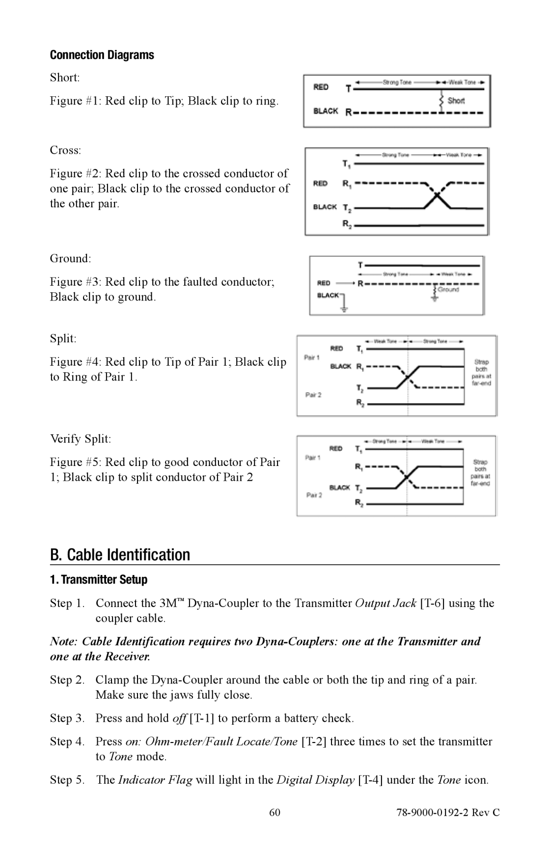
Short:
Figure #1: Red clip to Tip; Black clip to ring.
Cross:
Figure #2: Red clip to the crossed conductor of one pair; Black clip to the crossed conductor of the other pair.
Ground:
Figure #3: Red clip to the faulted conductor;
Black clip to ground.
Split:
Figure #4: Red clip to Tip of Pair 1; Black clip to Ring of Pair 1.
Verify Split:
Figure #5: Red clip to good conductor of Pair 1; Black clip to split conductor of Pair 2
B. Cable Identification
1. Transmitter Setup
Step 1. Connect the 3M™
Note: Cable Identification requires two
Step 2. Clamp the
Step 3. Press and hold off
Step 4. Press on:
Step 5. The Indicator Flag will light in the Digital Display
60 |
|