Step 8. With the receiver handle perpendicular to the conduit path, locate the ADP position by moving along the path until the strongest Signal Strength [9] ([8] for 2550 locator) is found. Adjust Gain [3] up or down when the Bar Graph
[11]([10] for 2550 locator) remains either fully open or fully closed. Step 9. Refer to the ADP operating instructions for further information.
A.Determining Active Duct Probe Depth
Step 1. Place the tip of the receiver on the ground directly above the located ADP position.
Step 2. Maintain the handle orientation perpendicular to the target path. Step 3. Press DEPTH [4].
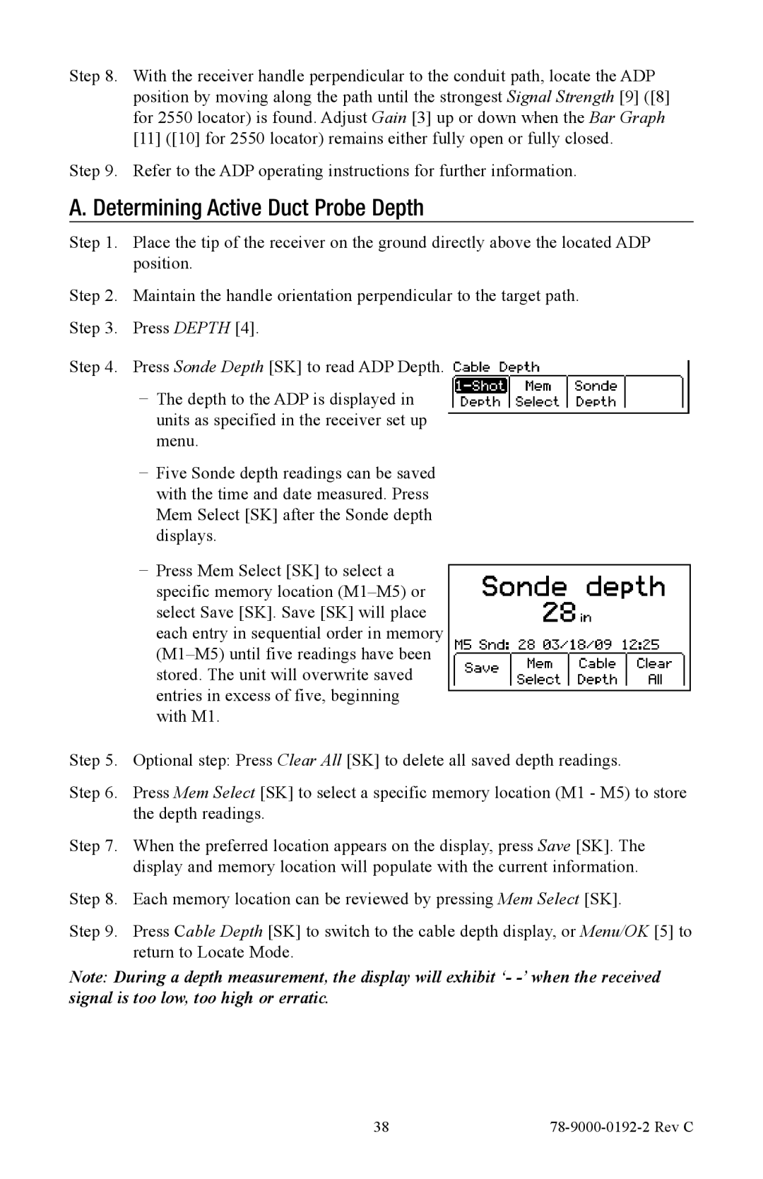
Step 4. Press Sonde Depth [SK] to read ADP Depth.
−− The depth to the ADP is displayed in units as specified in the receiver set up menu.
−− Five Sonde depth readings can be saved with the time and date measured. Press Mem Select [SK] after the Sonde depth displays.
−− Press Mem Select [SK] to select a specific memory location
Step 5. Optional step: Press Clear All [SK] to delete all saved depth readings.
Step 6. Press Mem Select [SK] to select a specific memory location (M1 - M5) to store the depth readings.
Step 7. When the preferred location appears on the display, press Save [SK]. The display and memory location will populate with the current information.
Step 8. Each memory location can be reviewed by pressing Mem Select [SK].
Step 9. Press Cable Depth [SK] to switch to the cable depth display, or Menu/OK [5] to return to Locate Mode.
Note: During a depth measurement, the display will exhibit ‘-
38 |
|