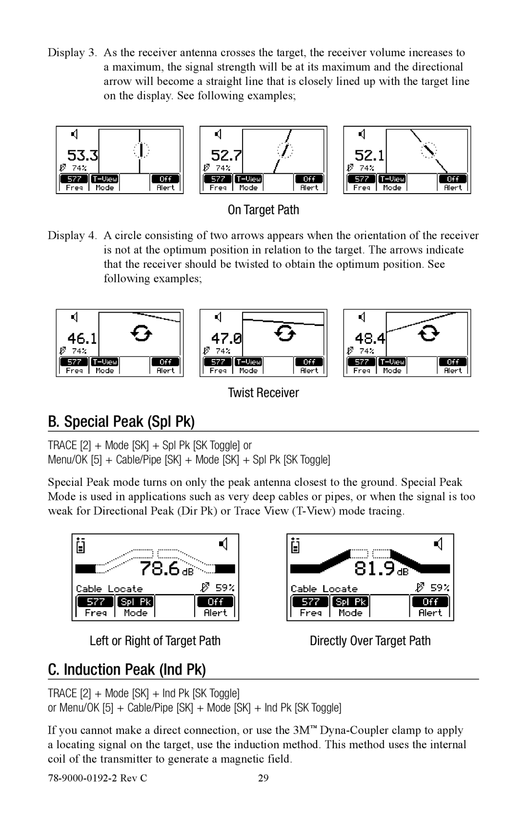
Display 3. As the receiver antenna crosses the target, the receiver volume increases to a maximum, the signal strength will be at its maximum and the directional arrow will become a straight line that is closely lined up with the target line on the display. See following examples;
On Target Path
Display 4. A circle consisting of two arrows appears when the orientation of the receiver is not at the optimum position in relation to the target. The arrows indicate that the receiver should be twisted to obtain the optimum position. See following examples;
Twist Receiver
B. Special Peak (Spl Pk)
TRACE [2] + Mode [SK] + Spl Pk [SK Toggle] or
Menu/OK [5] + Cable/Pipe [SK] + Mode [SK] + Spl Pk [SK Toggle]
Special Peak mode turns on only the peak antenna closest to the ground. Special Peak Mode is used in applications such as very deep cables or pipes, or when the signal is too weak for Directional Peak (Dir Pk) or Trace View
Left or Right of Target Path | Directly Over Target Path |
C. Induction Peak (Ind Pk)
TRACE [2] + Mode [SK] + Ind Pk [SK Toggle]
or Menu/OK [5] + Cable/Pipe [SK] + Mode [SK] + Ind Pk [SK Toggle]
If you cannot make a direct connection, or use the 3M™
29 |
