The Induction Peak mode of the receiver is a mode in which the upper antenna of the receiver is tuned to minimize distortion from the magnetic field of the transmitter.
Left or Right of Target Path | Directly Over Target Path |
D. Directional Peak (Dir Pk)
TRACE [2] + Mode [SK] + Dir Pk [SK Toggle]
or Menu/OK [5] + Cable/Pipe [SK] + Mode [SK] + Dir Pk [SK Toggle]
In Directional Peak mode, four peak antennas are used to analyze the magnetic field pattern. The bar graph indicates signal strength and the directional arrows sense the edges of the magnetic field. The left/right arrows will indicate the direction to the nearest cable/pipe that is
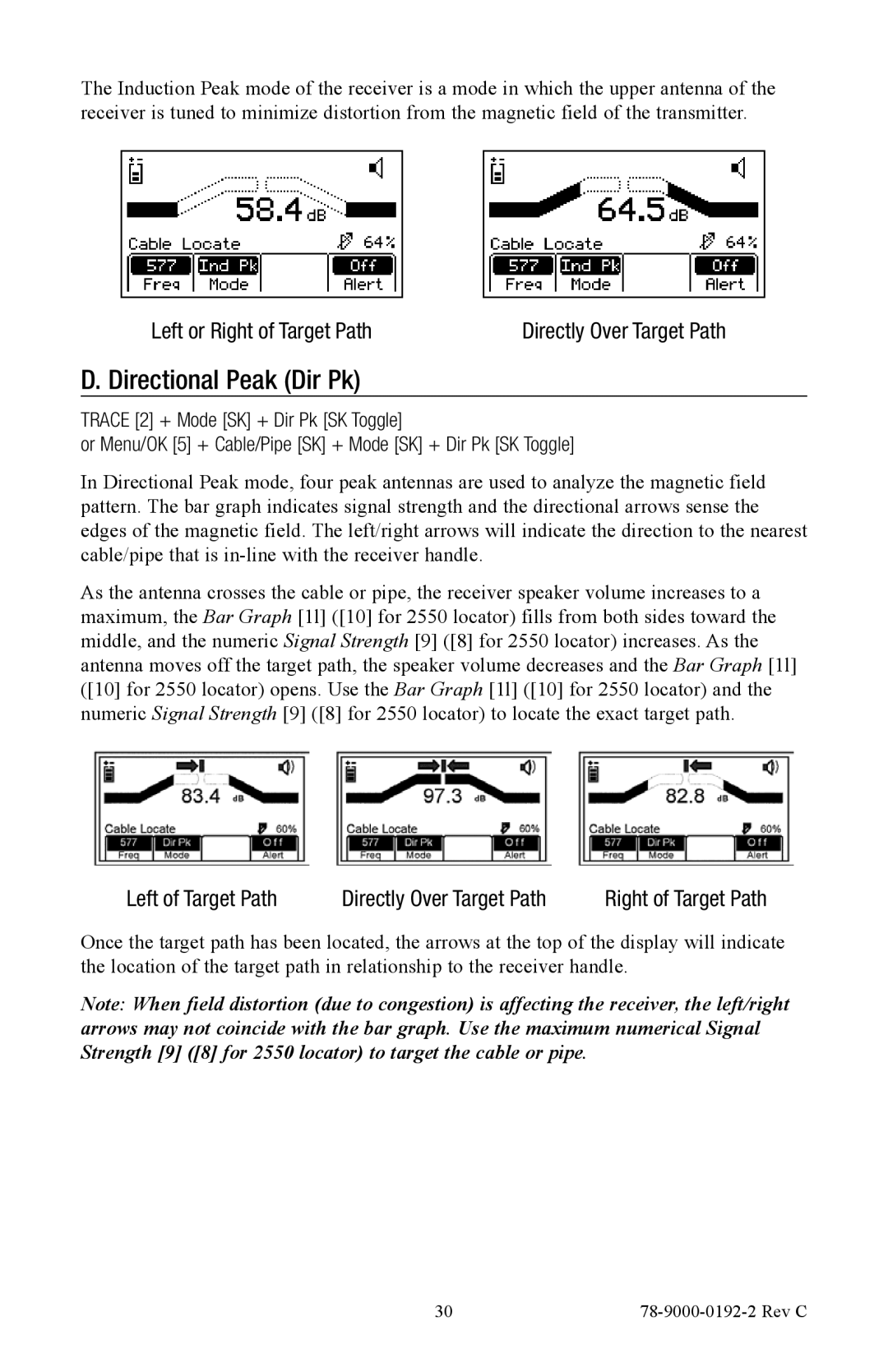
As the antenna crosses the cable or pipe, the receiver speaker volume increases to a maximum, the Bar Graph [1l] ([10] for 2550 locator) fills from both sides toward the middle, and the numeric Signal Strength [9] ([8] for 2550 locator) increases. As the antenna moves off the target path, the speaker volume decreases and the Bar Graph [1l] ([10] for 2550 locator) opens. Use the Bar Graph [1l] ([10] for 2550 locator) and the numeric Signal Strength [9] ([8] for 2550 locator) to locate the exact target path.
Left of Target Path | Directly Over Target Path | Right of Target Path |
Once the target path has been located, the arrows at the top of the display will indicate the location of the target path in relationship to the receiver handle.
Note: When field distortion (due to congestion) is affecting the receiver, the left/right arrows may not coincide with the bar graph. Use the maximum numerical Signal Strength [9] ([8] for 2550 locator) to target the cable or pipe.
30 |
|