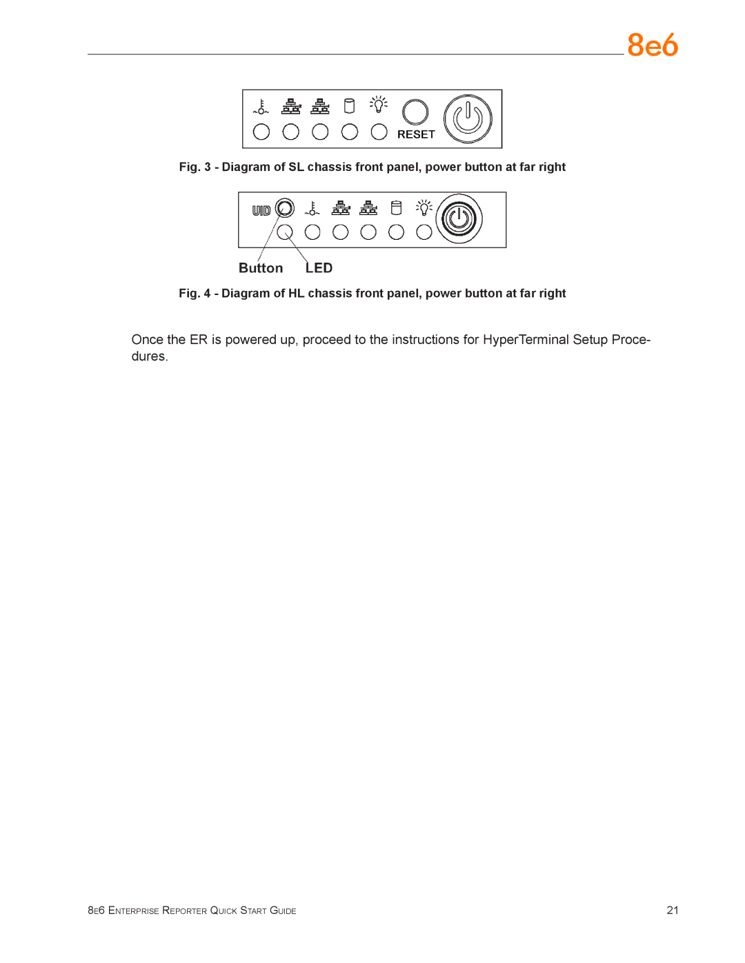
Fig. 3 - Diagram of SL chassis front panel, power button at far right
Fig. 4 - Diagram of HL chassis front panel, power button at far right
Once the ER is powered up, proceed to the instructions for HyperTerminal Setup Proce- dures.
8e6 Enterprise Reporter Quick Start Guide | 21 |
