Tap Installation
Install the Ethernet Tap Unit
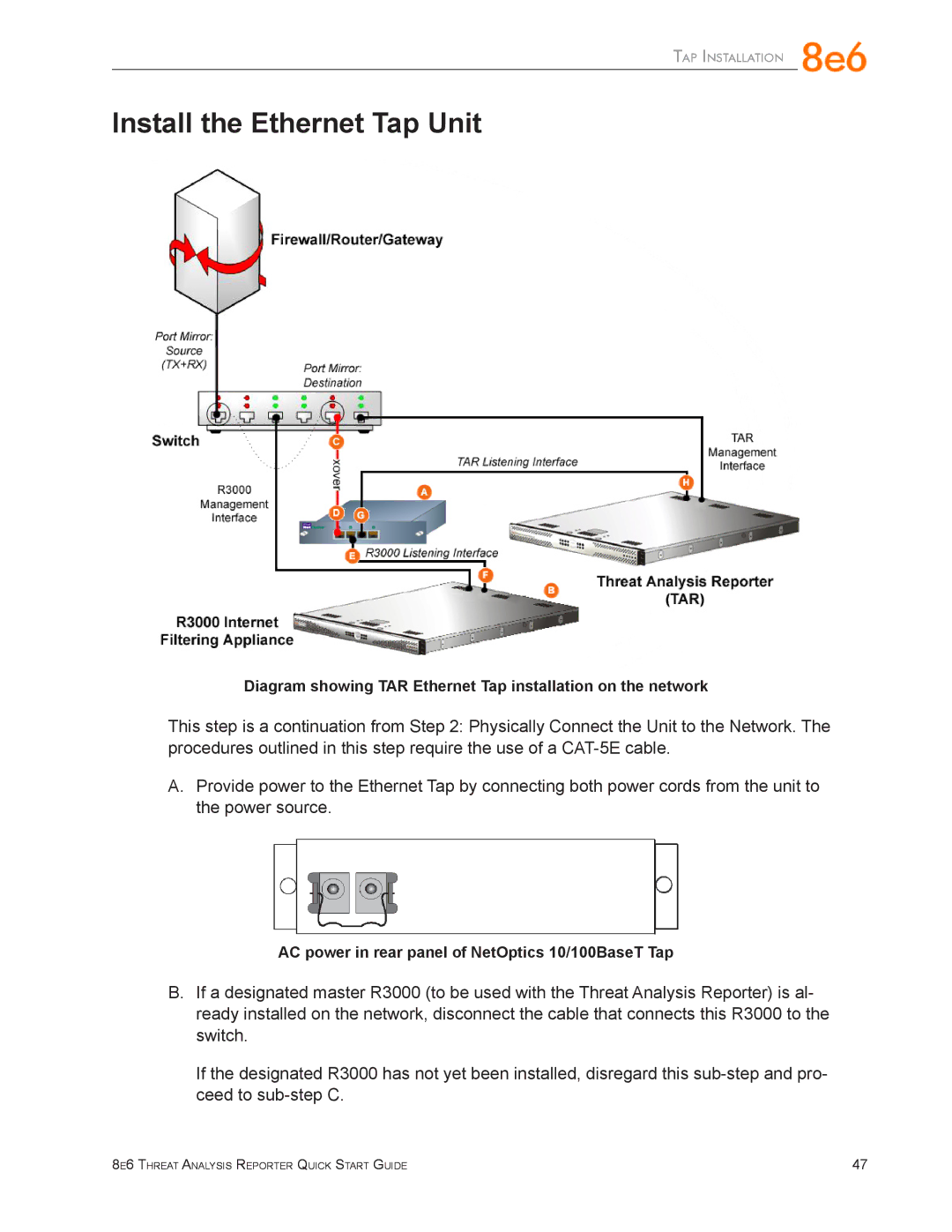
Diagram showing TAR Ethernet Tap installation on the network
This step is a continuation from Step 2: Physically Connect the Unit to the Network. The procedures outlined in this step require the use of a
A.Provide power to the Ethernet Tap by connecting both power cords from the unit to the power source.
AC power in rear panel of NetOptics 10/100BaseT Tap
B.If a designated master R3000 (to be used with the Threat Analysis Reporter) is al- ready installed on the network, disconnect the cable that connects this R3000 to the switch.
If the designated R3000 has not yet been installed, disregard this
8e6 Threat Analysis Reporter Quick Start Guide | 47 |