4. INSTALLATION and PRECAUTIONS
4-1. Precautions for Installing the Indicator
Ground the indicator so that the user will not be subjected an electric shock.
![]() Do not handle the main power cord with wet hands.
Do not handle the main power cord with wet hands.
![]() The AC plug is not
The AC plug is not ![]() Do not install the indicator where there is flammable or corrosive gas present.
Do not install the indicator where there is flammable or corrosive gas present.
Do not install the indicator under water.
Do not pull, fold or arrange cables forcibly.
Use shielded cables for all connections.
Ground the platform to be connected to the indicator to avoid a risk of electric shock.
Read the section “CAUTION” in the instruction manual of the
4-2. Load Cell Connections
Solder the load cell cable to the connector plug
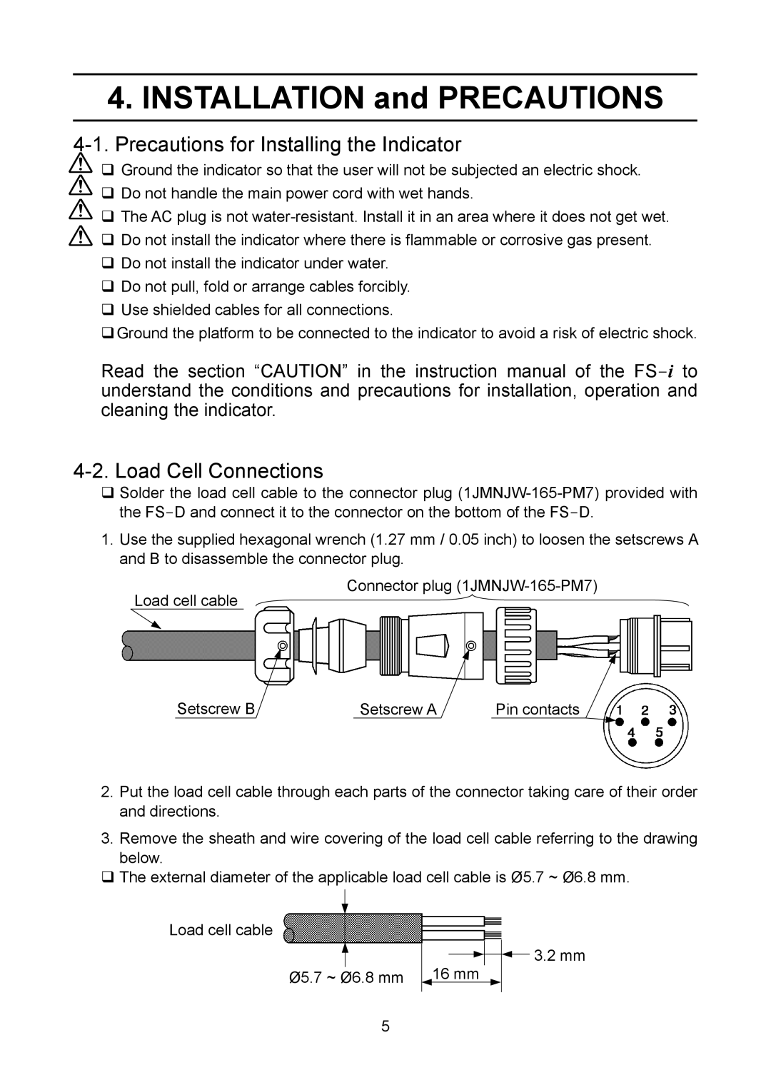
1.Use the supplied hexagonal wrench (1.27 mm / 0.05 inch) to loosen the setscrews A and B to disassemble the connector plug.
Connector plug
Load cell cable
Setscrew B | Setscrew A | Pin contacts |
2.Put the load cell cable through each parts of the connector taking care of their order and directions.
3.Remove the sheath and wire covering of the load cell cable referring to the drawing below.
The external diameter of the applicable load cell cable is Ø5.7 ~ Ø6.8 mm.
Load cell cable
Ø5.7 ~ Ø6.8 mm
16 mm
![]() 3.2 mm
3.2 mm
5