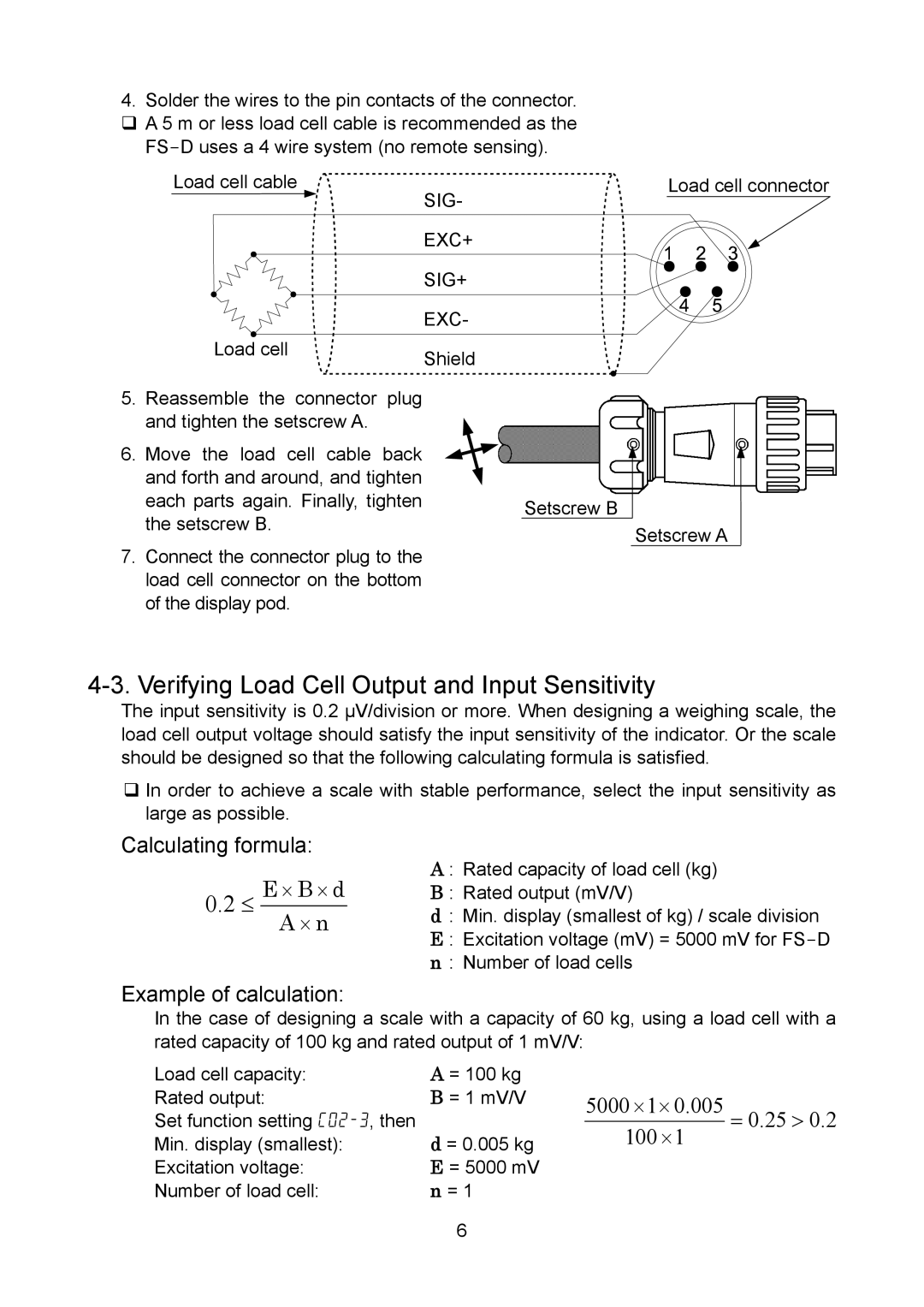
4.Solder the wires to the pin contacts of the connector. A 5 m or less load cell cable is recommended as the
Load cell cable
SIG-
Load cell connector
Load cell
5.Reassemble the connector plug and tighten the setscrew A.
6.Move the load cell cable back and forth and around, and tighten each parts again. Finally, tighten the setscrew B.
7.Connect the connector plug to the load cell connector on the bottom of the display pod.
EXC+
SIG+
EXC-
Shield
Setscrew B
Setscrew A
4-3. Verifying Load Cell Output and Input Sensitivity
The input sensitivity is 0.2 µV/division or more. When designing a weighing scale, the load cell output voltage should satisfy the input sensitivity of the indicator. Or the scale should be designed so that the following calculating formula is satisfied.
In order to achieve a scale with stable performance, select the input sensitivity as large as possible.
Calculating formula:
0.2≤ E ⋅ B ⋅ d A ⋅ n
A : Rated capacity of load cell (kg)
B : Rated output (mV/V)
d: Min. display (smallest of kg) / scale division E : Excitation voltage (mV) = 5000 mV for
Example of calculation:
In the case of designing a scale with a capacity of 60 kg, using a load cell with a rated capacity of 100 kg and rated output of 1 mV/V:
Load cell capacity: | A = 100 kg |
Rated output: | B = 1 mV/V |
Set function setting | d = 0.005 kg |
Min. display (smallest): | |
Excitation voltage: | E = 5000 mV |
Number of load cell: | n = 1 |
| 6 |
5000 ⋅1⋅ 0.005 | = 0.25 > 0.2 |
100 ⋅1 |
|