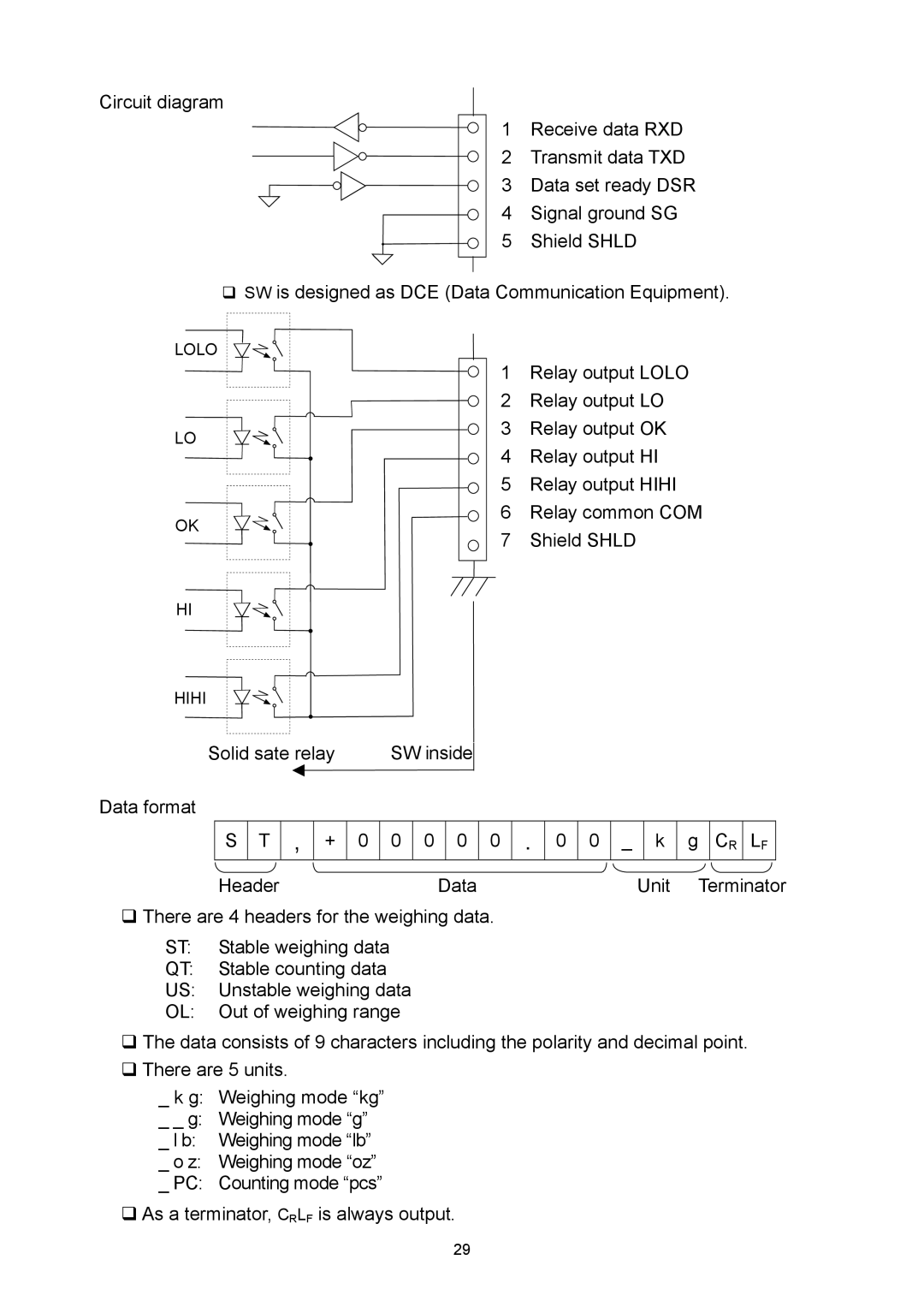
Circuit diagram
1 Receive data RXD
2 Transmit data TXD
3 Data set ready DSR
4 Signal ground SG
5 Shield SHLD
SW is designed as DCE (Data Communication Equipment).
LOLO |
|
LO |
|
OK |
|
HI |
|
HIHI |
|
Solid sate relay | SW inside |
1Relay output LOLO
2Relay output LO
3Relay output OK
4Relay output HI
5Relay output HIHI
6Relay common COM
7Shield SHLD
Data format
S T
,
+ 0 0 0 0 0
.
0 0 _ k g CR
LF
Header | Data | Unit Terminator |
There are 4 headers for the weighing data.
ST: Stable weighing data
QT: Stable counting data
US: Unstable weighing data
OL: Out of weighing range
The data consists of 9 characters including the polarity and decimal point.
There are 5 units.
_ k g: Weighing mode “kg”
_ _ g: Weighing mode “g”
_ l b: Weighing mode “lb”
_ o z: Weighing mode “oz”
_ PC: Counting mode “pcs”
As a terminator, CRLF is always output.
29
