The installation procedure is the same as for
Set the function settings “bp5”, “btpr”, “prt”, “5if”, “adr” and “aCk” as necessary.
Before using
To connect more than one scale to a computer, set a different address to each scale using the function setting “adr”.
13.3.2. OP-04 Specifications
|
|
|
|
|
|
|
|
|
|
|
| |||||
Transmission system | EIA |
|
|
|
|
|
|
|
|
| ||||||
Transmission form | Asynchronous, | |||||||||||||||
Data format | Baud rate: | 2400, 4800, 9600 bps | ||||||||||||||
| Data bits: | 7 bits + parity 1bit (EVEN / ODD) | ||||||||||||||
|
|
|
|
| or 8 bits (non parity) |
|
|
|
|
| ||||||
| Start bit: | 1 bit |
|
|
|
|
|
|
|
|
| |||||
| Stop bit: | 1 bit |
|
|
|
|
|
|
|
|
| |||||
| Code: | ASCII |
|
|
|
|
|
|
|
| ||||||
| Terminator: CRLF | (CR:0Dh, LF:0Ah) | ||||||||||||||
|
|
|
|
|
|
|
|
|
|
|
|
|
|
|
| |
|
|
| LSB |
|
|
|
|
|
| MSB |
|
|
|
| ||
|
|
| 0 |
| 1 |
| 2 | 3 | 4 | 5 | 6 |
|
|
|
| |
1
0(2V~15V)
Start bit | Data bits | Parity bit |
| Stop bit |
|
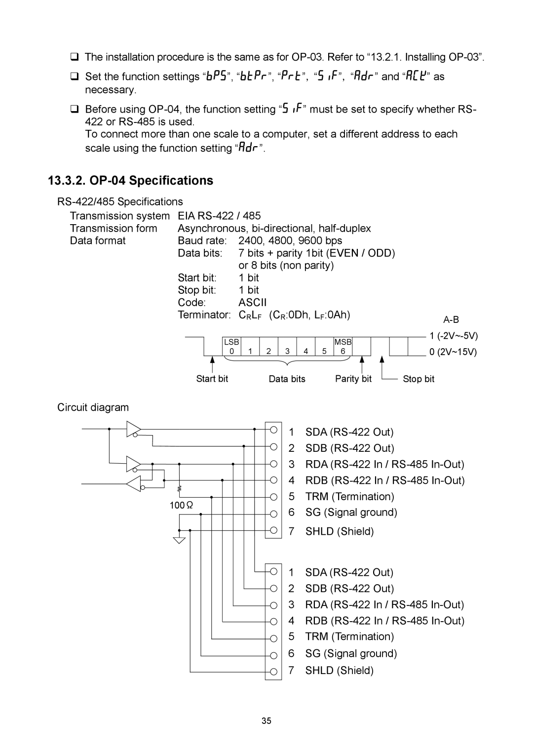
Circuit diagram
100Ω |
35 |
1SDA
2SDB
3RDA
4RDB
5TRM (Termination)
6SG (Signal ground)
7SHLD (Shield)
1SDA
2SDB
3RDA
4RDB
5TRM (Termination)
6SG (Signal ground)
7SHLD (Shield)