1.Disconnect the AC power cable from the electrical outlet. When the battery is installed, make sure that the scale is turned OFF.
2.Loosen the M4 screws and remove the rear cover of the display.
Note: Take care not to drop the display.
3.Connect the cables to the external device through the cable gland to the terminal blocks on the interface board.
4.Attach the connector cables (7 and 10 pins), provided with
5.Secure the interface board using the two M3 x 8 screws provided with
6.Tighten the cable glands and attach the rear cover to the display and secure it with the screws loosened at step 2.
7.Connect the AC power cable to the electrical outlet.
8.Set the function settings “bp5”, “btpr”, “prt”. “5if” and “aCk” as necessary.
To use the
13.2.2. OP-03 Specifications
|
| |
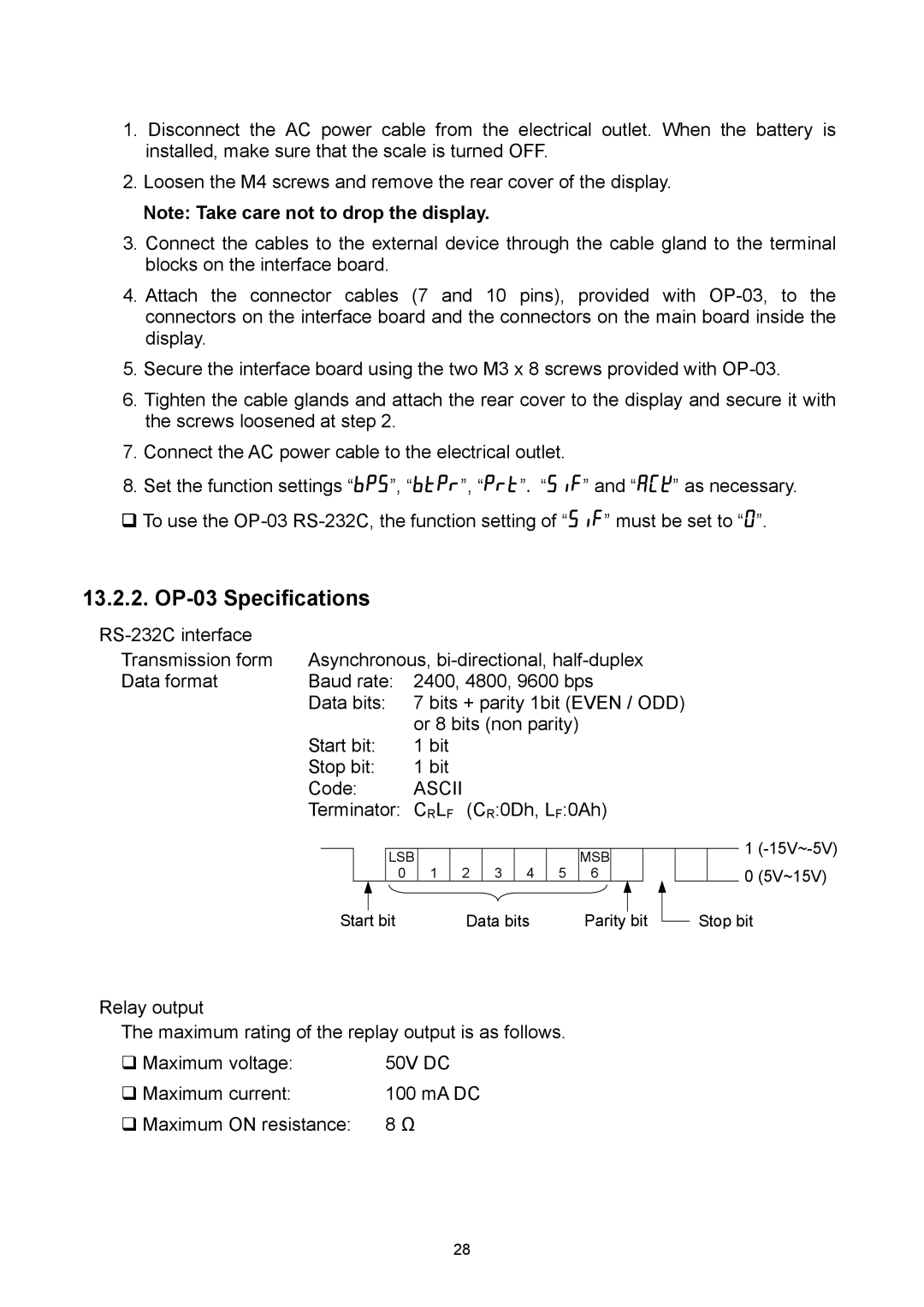
Transmission form | Asynchronous, | |
Data format | Baud rate: | 2400, 4800, 9600 bps |
| Data bits: | 7 bits + parity 1bit (EVEN / ODD) |
|
| or 8 bits (non parity) |
| Start bit: | 1 bit |
| Stop bit: | 1 bit |
| Code: | ASCII |
| Terminator: | CRLF (CR:0Dh, LF:0Ah) |
|
|
|
| LSB |
|
|
|
|
| MSB |
|
|
|
|
|
|
|
| 0 | 1 | 2 | 3 | 4 | 5 | 6 |
|
|
|
|
|
|
|
|
|
|
| ||||||||
Start |
| bit |
| Data bits |
| Parity |
| bit | ||||||
|
|
|
| |||||||||||
1
0(5V~15V)
Stop bit
Relay output
The maximum rating of the replay output is as follows.
Maximum voltage: | 50V DC |
Maximum current: | 100 mA DC |
Maximum ON resistance: | 8 Ω |
28