2
22
47
18
48
9
11
10
24
49
12
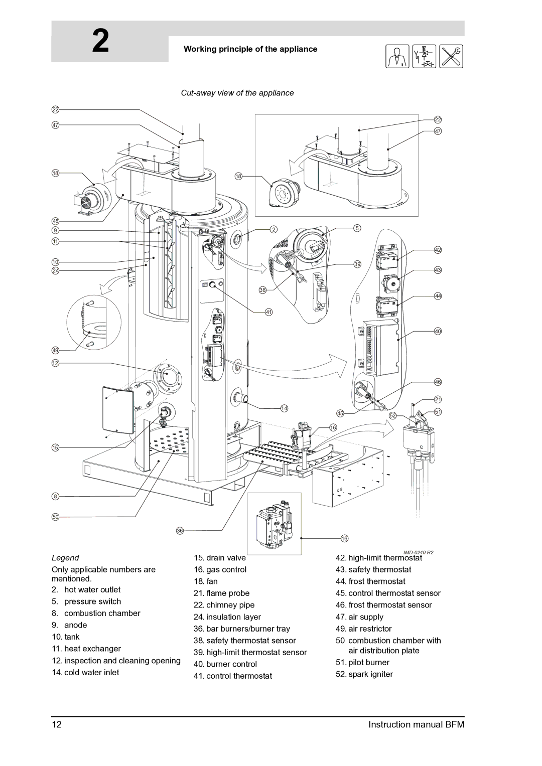
Working principle of the appliance | gis |
|
|
| 22 |
|
| 47 |
18 |
|
|
2 | 5 |
|
|
| 42 |
| 39 | 43 |
|
| |
38 |
| 44 |
|
| |
41 |
|
|
|
| 40 |
|
| 46 |
|
| 21 |
14 |
| 51 |
45 | 52 | |
|
| |
16 |
|
|
15
8 |
|
|
| |
50 |
|
|
| |
| 36 |
|
| |
|
|
| 16 | |
Legend | 15. drain valve | |||
42. | ||||
Only applicable numbers are | 16. gas control | 43. safety thermostat | ||
mentioned. | 18. fan | 44. frost thermostat | ||
2. | hot water outlet | |||
21. flame probe | 45. control thermostat sensor | |||
5. | pressure switch | |||
22. chimney pipe | 46. frost thermostat sensor | |||
8. | combustion chamber | |||
24. insulation layer | 47. air supply | |||
9. | anode | |||
36. bar burners/burner tray | 49. air restrictor | |||
10. tank | ||||
38. safety thermostat sensor | 50 combustion chamber with | |||
11. heat exchanger | ||||
39. | air distribution plate | |||
12. inspection and cleaning opening | 40. burner control | 51. pilot burner | ||
14. cold water inlet | 41. control thermostat | 52. spark igniter | ||
12 | Instruction manual BFM |