2
Working principle of the appliance
•the Water temperature protection;
•the Flame probe;
•the Pressure switch.
gis
2.4.2Water temperature protection
By means of the frost,
Temperature protection
Protection | Description |
|
|
Frost thermostat | When the frost thermostat sensor (46) measures a temperature of 20°C or |
| less, the heating cycle (2.3 "The appliance's heating cycle") will start. |
|
|
When the | |
| than 84°C, the |
| and the burner control halts the heating cycle until the |
| close once more. At that moment the burner control will reset the appliance and |
| the heating cycle will restart. The |
| overheating and/or excessive formation of scale in the appliance. |
|
|
Safety thermostat | When the safety thermostat sensor (38) measures a temperature higher than |
| 93°C, the safety thermostat will open. The heat demand is terminated and the |
| burner control will immediately halt the heating cycle. The burner control will go |
| into a lockout error state. This must be manually reset before the appliance can |
| resume operation. |
|
|
2.4.3Pressure switch
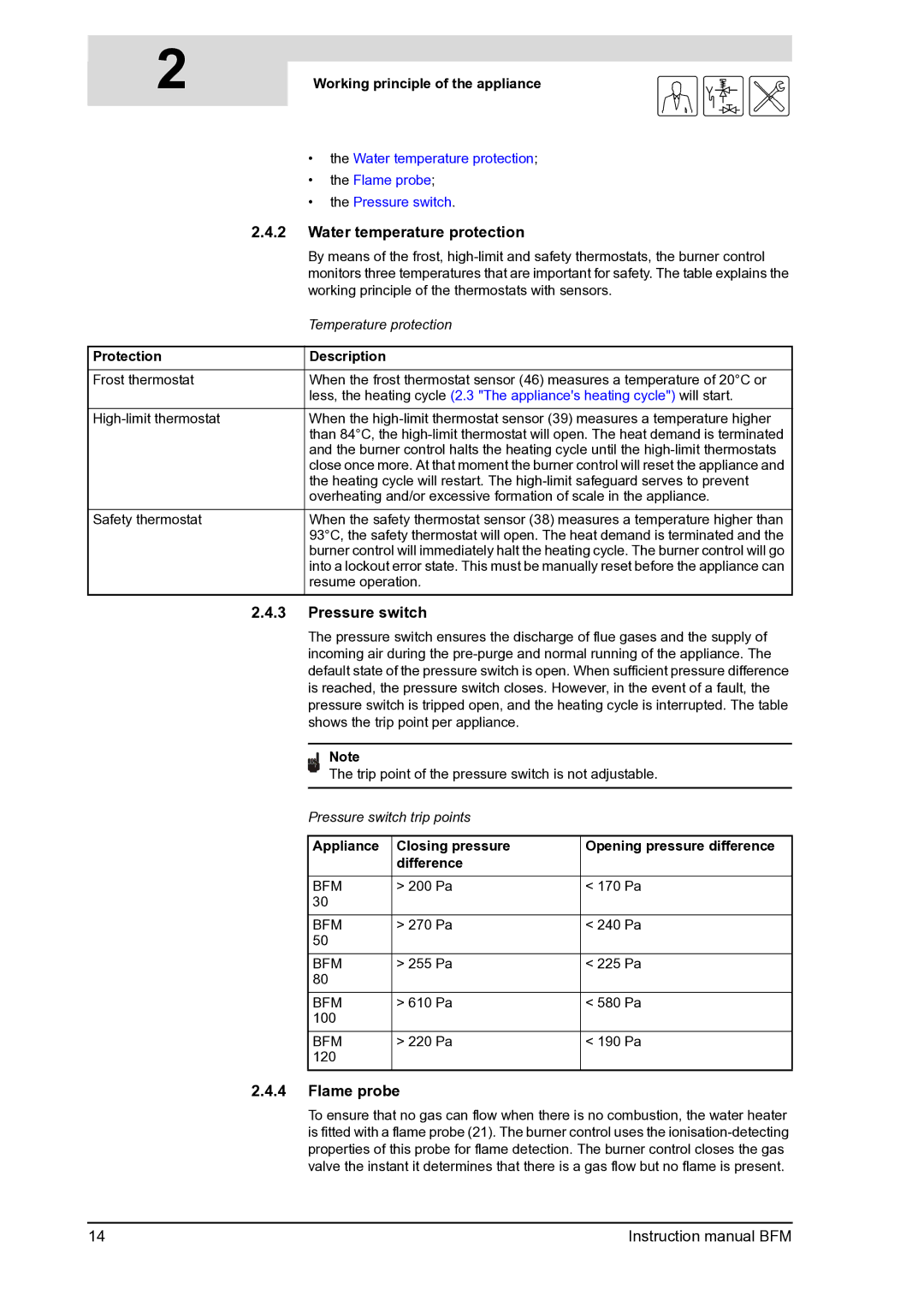
The pressure switch ensures the discharge of flue gases and the supply of incoming air during the
Note
The trip point of the pressure switch is not adjustable.
Pressure switch trip points
Appliance | Closing pressure | Opening pressure difference |
| difference |
|
|
|
|
BFM | > 200 Pa | < 170 Pa |
30 |
|
|
|
|
|
BFM | > 270 Pa | < 240 Pa |
50 |
|
|
|
|
|
BFM | > 255 Pa | < 225 Pa |
80 |
|
|
|
|
|
BFM | > 610 Pa | < 580 Pa |
100 |
|
|
|
|
|
BFM | > 220 Pa | < 190 Pa |
120 |
|
|
|
|
|
2.4.4Flame probe
To ensure that no gas can flow when there is no combustion, the water heater is fitted with a flame probe (21). The burner control uses the
14 | Instruction manual BFM |
