7.Replace the Camera Module cable bundle in the casing as shown.
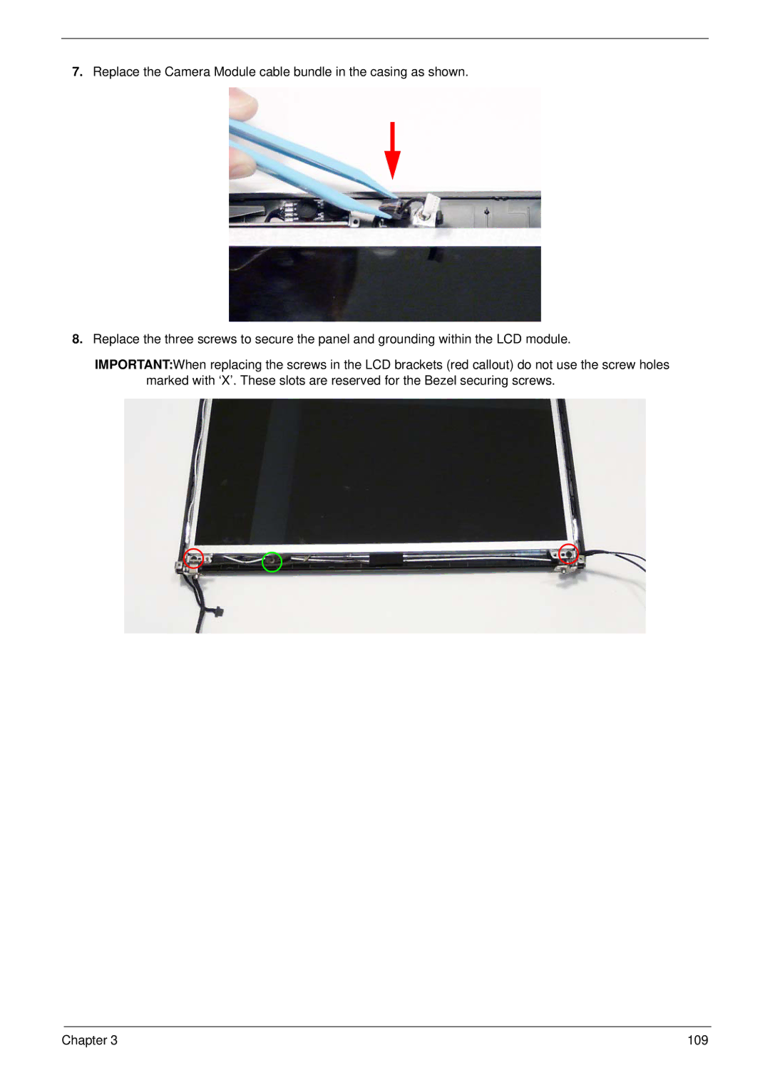
8.Replace the three screws to secure the panel and grounding within the LCD module.
IMPORTANT:When replacing the screws in the LCD brackets (red callout) do not use the screw holes marked with ‘X’. These slots are reserved for the Bezel securing screws.
Chapter 3 | 109 |