Removing the Switch Cover
CAUTION: Using tools to remove the Switch Cover may cause damage to the outer casing. It is recommended that only fingers are used to remove the Switch Cover.
1.See “Removing the Battery Pack” on page 52.
2.See “Removing the Hinge Covers” on page 64.
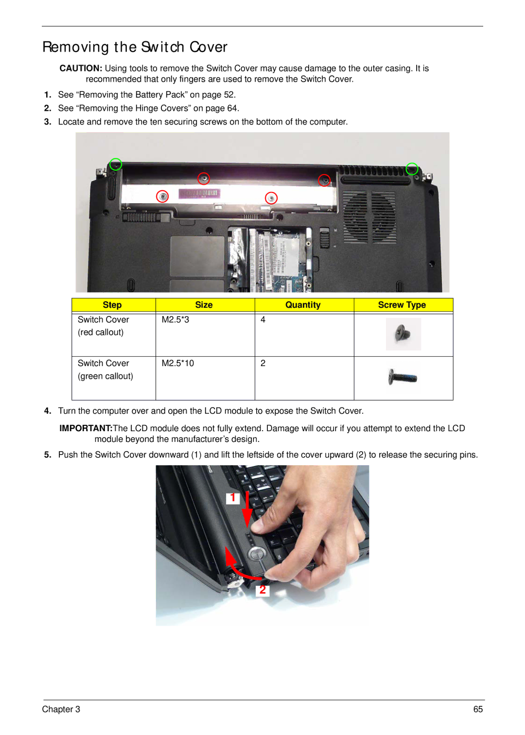
3.Locate and remove the ten securing screws on the bottom of the computer.
Step | Size | Quantity | Screw Type |
|
|
|
|
Switch Cover | M2.5*3 | 4 |
|
(red callout) |
|
|
|
|
|
|
|
Switch Cover | M2.5*10 | 2 |
|
(green callout) |
|
|
|
|
|
|
|
4.Turn the computer over and open the LCD module to expose the Switch Cover.
IMPORTANT:The LCD module does not fully extend. Damage will occur if you attempt to extend the LCD module beyond the manufacturer’s design.
5.Push the Switch Cover downward (1) and lift the leftside of the cover upward (2) to release the securing pins.
1
2
Chapter 3 | 65 |
